
Defogging device for a surveillance camera

a technology of defogging device and surveillance camera, which is applied in the direction of television system, instruments, transportation and packaging, etc., can solve the problem of reducing the effectiveness of surveillance cameras

Inactive Publication Date: 2007-05-17
CHENG YI JEN
View PDF2 Cites 75 Cited by
  • Summary
  • Abstract
  • Description
  • Claims
  • Application Information

AI Technical Summary

Benefits of technology

[0009] The main objective of the present invention is to provide a defogging device to remove fog or frost from a lens of a surveillance camera or keep fog or frost from forming on the lens.

Problems solved by technology

The fog or frost keeps the camera lens from obtaining a clear image through the lens or lens cover on the case and reduces the effectiveness of the surveillance camera.

Method used


Image

  • Defogging device for a surveillance camera
  • Defogging device for a surveillance camera
  • Defogging device for a surveillance camera

Examples


Embodiment Construction

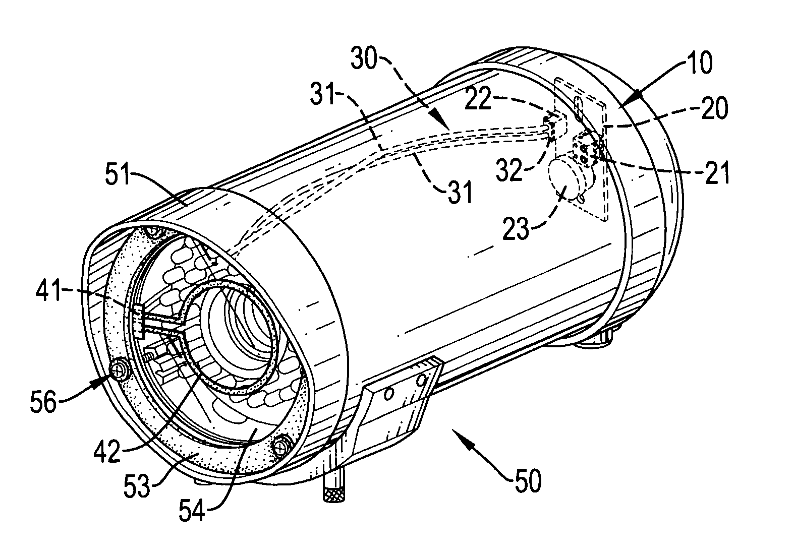
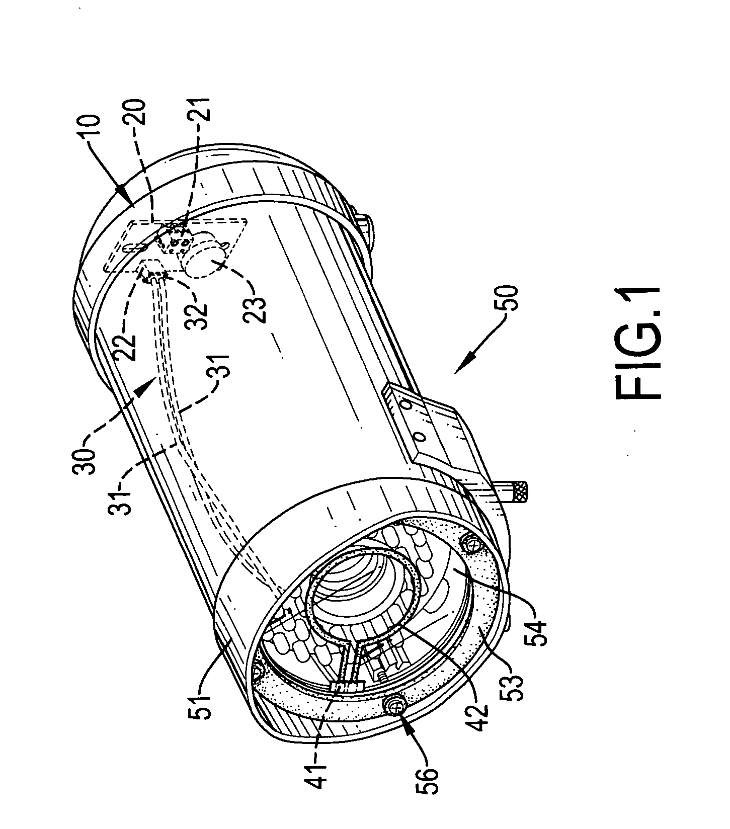
[0016] With reference to FIG. 1, a defogging device (10) in accordance with the present invention for a surveillance camera removes fog or frost from a lens of the surveillance camera.

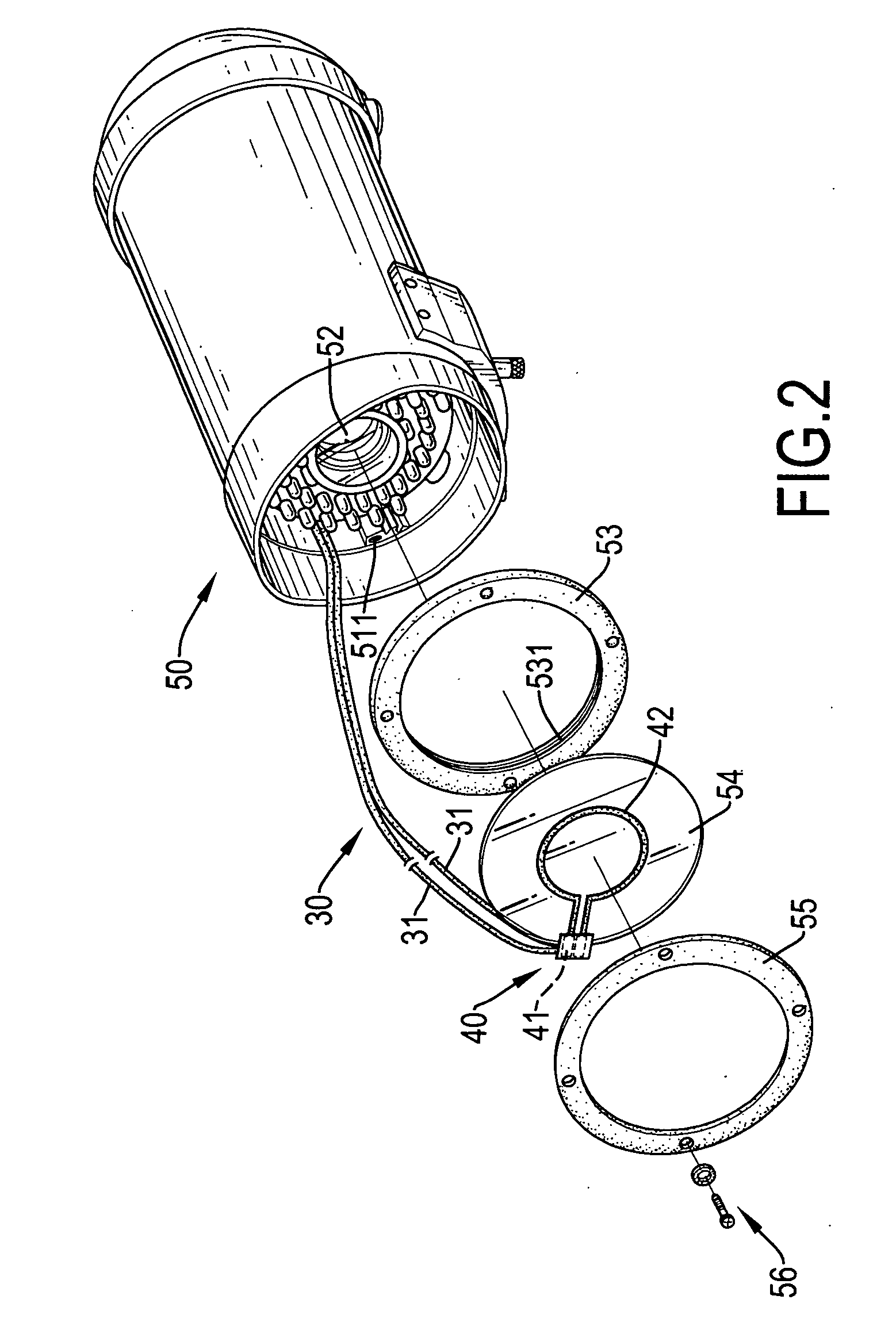
[0017] With further reference to FIG. 2, the surveillance camera (50) having a case (51), a camera (52), a washer (53), a lens cover (54), a retaining ring (55) and multiple fasteners (56).

[0018] The case (51) has a front end, an inner cavity, an inner surface and multiple threaded seats (511). The threaded seats (511) are formed on and protrude in from the inner surface near the front end of the case (51) and each threaded seat (511) has a threaded hole facing the front end.

[0019] The camera (52) is mounted in the inner cavity of the case (51) and has a lens, a camera mechanism and a power source.

[0020] The washer (53) is mounted in the front end of the case (51) against the threaded seats (511) and has an inside surface and an annular groove (531). The annular groove (531) is formed in the inside...


PUM


Abstract

A defogging device for a surveillance camera has a heating element, a circuit board and a power cord. The heating element is mounted over the lens of the surveillance camera. The circuit board compares ambient temperature to a preset temperature, activates the heating element and has a power input terminal, a power output terminal and a temperature sensor. The temperature sensor is mounted between the power input terminal and the power output terminal and senses ambient temperature. When the ambient temperature is above the preset temperature, the circuit board activates the heating element. The power cord is connected to the circuit board and the heating element and transmits power to the heating element from the circuit board. By activating the heating element during periods of cold ambient temperature, the defogging device removes fog and frost from or keeps fog and frost from forming on the lens of the surveillance camera.

Description

BACKGROUND OF THE INVENTION [0001] 1. Field of the Invention [0002] The present invention relates to a defogging device, and more particularly to a defogging device for a surveillance camera. [0003] 2. Description of Related Art [0004] Conventional surveillance cameras are widely used. To protect the camera lens and keep the camera lens from getting dirty, lenses are often mounted inside surveillance camera cases. Therefore the influence of the external environment on the lens are reduced or eliminated. [0005] However, the conventional surveillance camera has the following shortcomings. [0006] 1. In countries in the temperate zone of the earth, fog or frost on the lens or lens cover on the case of the surveillance camera during periods of lower temperature. [0007] 2. The fog or frost keeps the camera lens from obtaining a clear image through the lens or lens cover on the case and reduces the effectiveness of the surveillance camera. [0008] The defogging device for a surveillance cam...

Claims


Application Information

Patent Timeline
IPC IPC(8): H04N5/225
CPCG08B13/19619G08B13/19636H04N5/2251
Inventor CHENG, YI-JEN
Owner CHENG YI JEN
Learn More