
Automotive drive comprising a water-based retarder

a technology of retarder and water-based technology, which is applied in the direction of liquid resistance brakes, brake types, braking systems, etc., can solve the problems of idling inability to use, and high cost of precisely manufactured elements, so as to prevent the effect of power loss of retarder

Inactive Publication Date: 2007-05-10
VOITH TURBO GMBH & CO KG
View PDF7 Cites 23 Cited by
  • Summary
  • Abstract
  • Description
  • Claims
  • Application Information

AI Technical Summary

Benefits of technology

[0009] The present invention further provides a retarder that improves on the equipment cost of current retarders by using less expensive parts.
[0010] The present invention still further provides a long-life retarder whose components do not have to be replaced frequently.
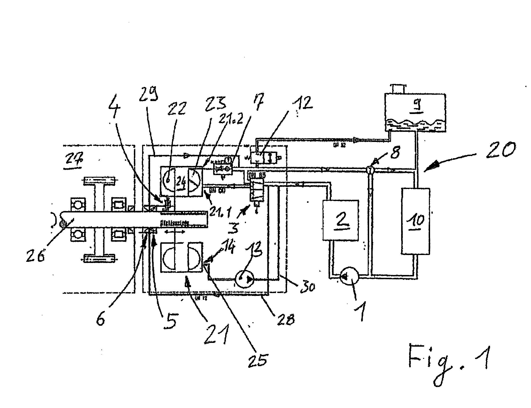
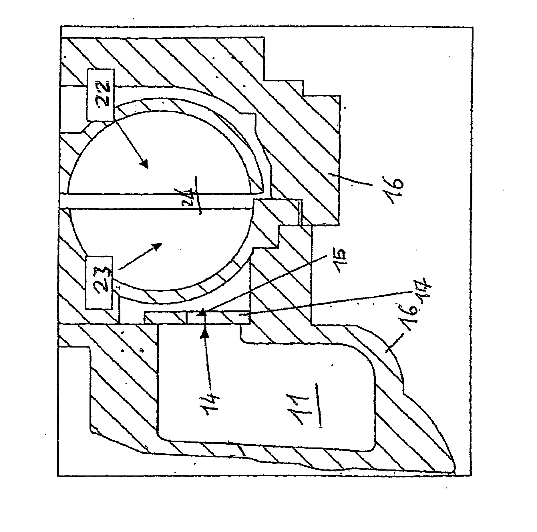
[0014] The arrangement of the leakage pump in the present invention precludes the need for absolutely leak-tight seals and, if need be, valves that seal the working chamber of the retarder. This is especially true for those seals and valves that are impinged on both sides by the coolant of the cooling circuit. Such seals and / or valves include the shaft seals of the retarder rotor, which are lubricated and / or cooled by the coolant of the motor vehicle, and the valves that close off the branch of the cooling circuit in which the retarder is disposed from the remaining cooling circuit of the motor vehicle.
[0015] With respect to the rotor seals that are exposed to coolant, it is even possible to adjust a predetermined leakage flow into the working chamber of the retarder during non-braking operation, this leakage flow being discharged once again by the leakage pump arranged in accordance with the invention. The retarder and the shaft seal(s) are effectively cooled by this leakage flow, because heat is dissipated via this leakage flow into the cooling circuit of the motor vehicle. Finally, because the leakage pump maintains an optimal residual amount of working medium in the retarder during non-braking operation, power loss of the retarder during idling is reliably prevented, in spite of the lack of tightness of the seals of the working chamber.
[0016] The shaft seals that seal the retarder against the surroundings are advantageously constructed in an absolutely leak-tight manner in order to prevent an uncontrolled escape of coolant or working medium from the retarder into the ambient surroundings.
[0017] The leakage pump arranged in accordance with the invention is driven by an electric motor, the retarder shaft, or the compressed air supply of the motor vehicle. Preferably, the leakage pump is disposed directly on the retarder shaft, so that it is possible to dispense with interposed elements that transmit the drive torque. In this way, the leakage pump is driven with particularly low power loss. In an especially preferred embodiment, it is possible to dispense with an additional drive for the leakage pump by constructing the leakage pump as a water-jet pump that is integrated into the cooling circuit of the motor vehicle. In such a construction, the drive work of the leakage pump is performed indirectly by the water pump arranged in the cooling circuit of the motor vehicle. It is also preferred to provide a bypass in order to circumvent the leakage pump during braking operation of the retarder, because working medium can then be discharged from the working chamber of the retarder exclusively via the outlet mentioned for discharging the working medium.

Problems solved by technology

There are several drawbacks to an absolute leak-tightness of all elements that seal the working chamber, such as the shaft seals or valves arranged in the cooling circuit that close off the branch of the cooling circuit in which the retarder is disposed from the remaining cooling circuit during non-braking operation.
Extremely high-grade, precisely manufactured elements, which are expensive, can only be used.
In addition, even slight wear after a short period of operation leads to the necessity of replacing these elements.

Method used


Image

  • Automotive drive comprising a water-based retarder
  • Automotive drive comprising a water-based retarder
  • Automotive drive comprising a water-based retarder

Examples


Embodiment Construction

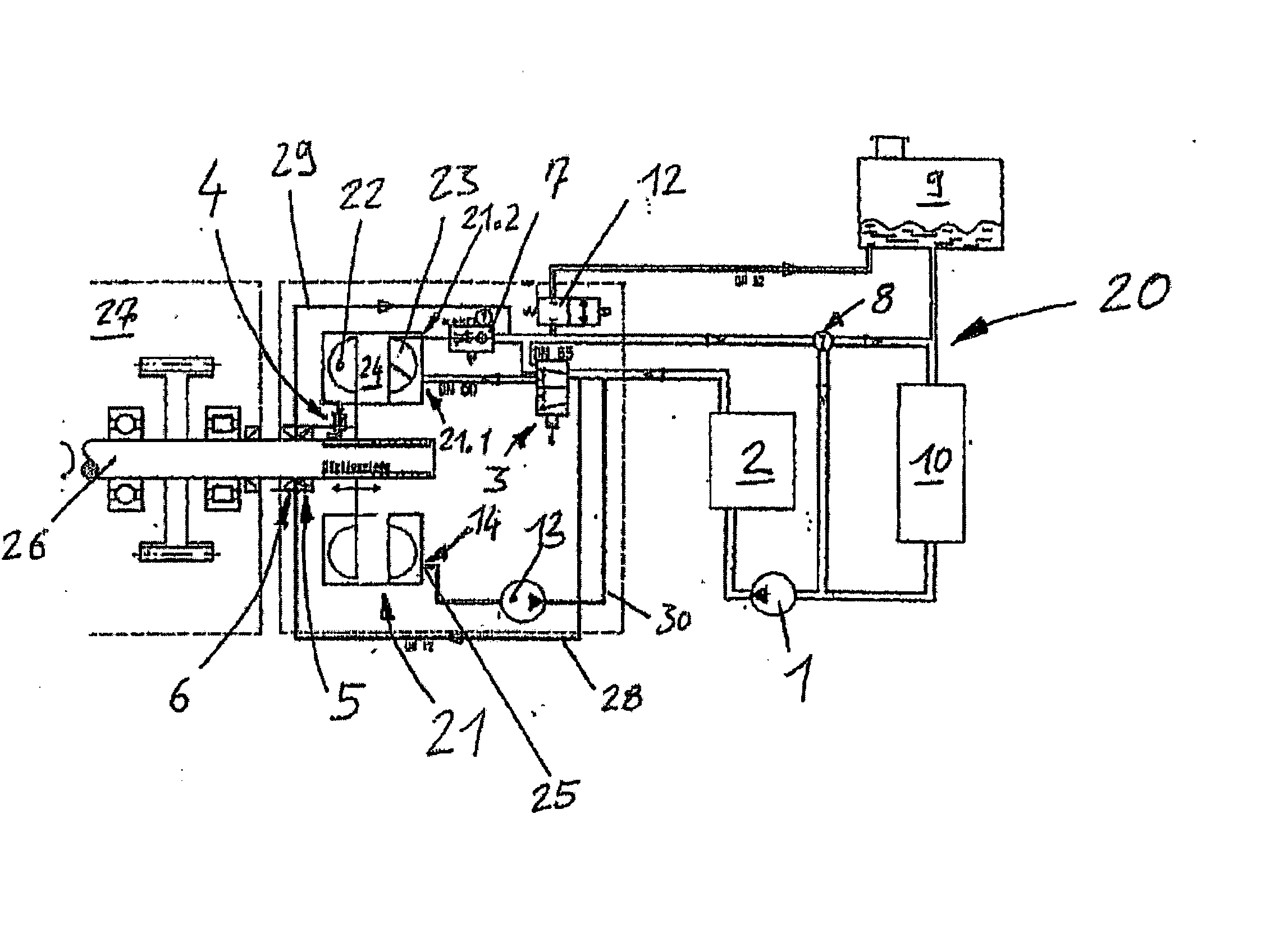
[0022] Referring to FIG. 1, a cooling circuit 20 of the automotive drive of the present invention is shown. A coolant is circulated by means of a cooling water pump 1 in the cooling circuit. In the shown embodiment, the coolant is water or a water-glycol mixture. However, the present invention contemplates the use of any coolant that would be suitable for such an automotive drive.

[0023] By means of the coolant, an engine 2 is cooled and simultaneously, during braking operation, a retarder 21 is operated. The coolant in turn is cooled by means of a radiator 10, which is can be a conventional motor vehicle radiator. A thermostat or a thermostatic valve 8 is disposed in the direction of flow (noted by the directional arrows in FIG. 1) in front of the radiator 10, and divides the flow of coolant into a line to the radiator 10 and a bypass to radiator 10. The amount of coolant allowed to pass into radiator 10 and / or the bypass line depends on the amount of cooling required and is contro...


PUM


Abstract

The invention relates to an automotive drive, comprising a cooling circuit with a coolant, a retarder having a rotor and a stator that together form a toroidal working chamber, with the coolant being the working medium of the retarder. The retarder has an inlet for feeding the working medium from the cooling circuit and an outlet for discharging the working medium into the cooling circuit. The present automotive drive is characterized by the following features: the retarder has an additional evacuation outlet, which communicates with the cooling circuit so as to carry the working medium; a leakage pump is interposed in the connection between the evacuation outlet and the cooling circuit.

Description

BACKGROUND OF THE PRESENT INVENTION [0001] 1. Field of the Invention [0002] The present invention relates to an automotive drive with a water retarder. The invention relates, in particular, to a device and a method for adjusting the optimal residual quantity of working medium in the working chamber of the retarder during non-braking operation. [0003] 2. Description of the Related Art [0004] Retarders have been widely known in the art for a long time. Traditionally, conventional retarders have been operated with oil as the working medium. There has recently been an increasing tendency, however, to place the retarder directly in the cooling circuit of the motor vehicle and to utilize the coolant of the motor vehicle simultaneously as the working medium of the retarder. This is advantageous because it makes it possible to dispense with a separate oil circuit for operating the retarder. The heat that accumulates in the retarder can be dissipated directly via the cooling circuit of the m...

Claims


Application Information

Patent Timeline
IPC IPC(8): F16D57/02B60T10/02
CPCB60T10/02B60T10/00
Inventor LAUKEMANN, DIETER
Owner VOITH TURBO GMBH & CO KG
Learn More