
Apparatus for a litter box

Active Publication Date: 2007-04-26
AUTOMATED PET CARE PROD LLC
View PDF29 Cites 8 Cited by
  • Summary
  • Abstract
  • Description
  • Claims
  • Application Information

AI Technical Summary

Benefits of technology

[0011] Accordingly, it is an object of the present invention to provide an automatic litter box to employ a superior cleaning method that uses a screen and a temporary container, as well as a method for altering the relationship of the appropriate components relative to the vector force of gravity.

Problems solved by technology

The major flaw with the raking method is that a motor forces not only the rake through litter, but also the solid waste material though the litter as well.
Although the rake can be made in such a way to travel relatively easily through litter, the unpredictable shapes and generally large surface area of solid waste makes it difficult to force waste clumps through such a dense and heavy material such as clay litter.
The typical behavior of cats to bury their clumps makes this process even more difficult.
There are often many undesirable effects with using such a raking method.
One such effect is that clumps and other solid material can be wedged between the rack and the bottom of the litter pan, which can cause a smearing effect.
The gradual build-up of such debris makes subsequent raking phases more and more difficult.
In this scenario, gravity is actually hindering the filtering process.
The options for which direction the litter can move are reduced, and further smearing can occur, and the increased force on the debris can further force the debris into the tines of the rake, clogging the rake.
This makes it extremely difficult for the rake to filter the unevenly covered litter pan.
Because of these problems, there is usually a narrow range at which the litter must be maintained.
To high a level, and the force required to push the rake and the debris through the litter is too great for the device to handle.
Aside from a clogged rake making the litter box ineffective, it also increases stress on the mechanical parts, motor, and power consumption.
It is also extremely difficult to unclog the rake, as well as being an extremely undesirable task to take on.
U.S. Pat. No. 6,851,386 tries to address this problem by introducing a rake that is less susceptible to clogging; however the raking method itself cannot change the force of gravity working against the debris or the mass of the clay.
This results in an incomplete cleaning process.
Being an enclosed litter box, this product does have the advantage of making it far more difficult for the cat to throw litter outside of the litter box; however there are also significant disadvantages as well.
Secondly, this product must have ports in the globe that open to let waste exit the globe and fall into the waste receptacle.
These ports limit the size of the clumps that can fit through these the ports, preventing the use of the device for cats that create large clumps; this particularly true for cats with diabetes, as the clumps will not fit through the ports.
Thirdly, it is relatively difficult to introduce fresh litter into the globe as well as clean the globe (which is recommended to be done periodically).
A cat less than 5 lbs. will not weigh enough to trigger the sensor, and cats over 15 lbs. will have trouble fitting into the globe.
This has the significant advantage of using the sifting method while still providing a traditional open litter box that's attractive to the largest population of cats; however this mechanism has multiple disadvantages, the first of which is that the device would have to be very large in order to create a litter area large enough for a typical feline to use effectively.
The second disadvantage is that the mechanism is not automated, and would be difficult to automate.
The third disadvantage is that it is would be very difficult to level the litter without picking up the entire litter box and shaking it around.
A litter box is only effective if the cat will use the device, and because many cats will simply not uses enclosed litter boxes, a perfectly designed enclosed system will not do the job if the cat does not elect to use it.
For those cats that will not use an enclosed device, the alternative is that the cat will either use an unenclosed litter box if available, or an undesirable location if not available.
This makes it even more difficult to get the value out of a potentially expensive enclosed litter box device if a pet owner has multiple cats.
However, because many cats that would otherwise use the enclosed device if that were their only option will often use the unenclosed device when given the choice, the effectiveness of the enclosed device is further reduced, as it gets used even less frequently than expected by the cat owner.
The challenge is thus to create an automated litter box that has superior filtering capabilities by utilizing the sifting method, and yet has an open design to encourage use by as many household pets as possible.

Method used


Image

  • Apparatus for a litter box
  • Apparatus for a litter box
  • Apparatus for a litter box

Examples


Embodiment Construction

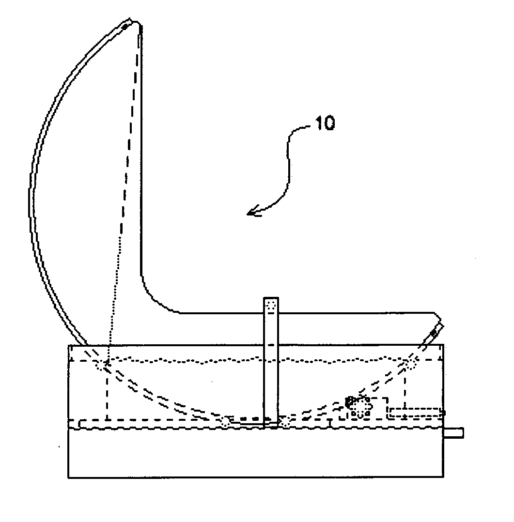
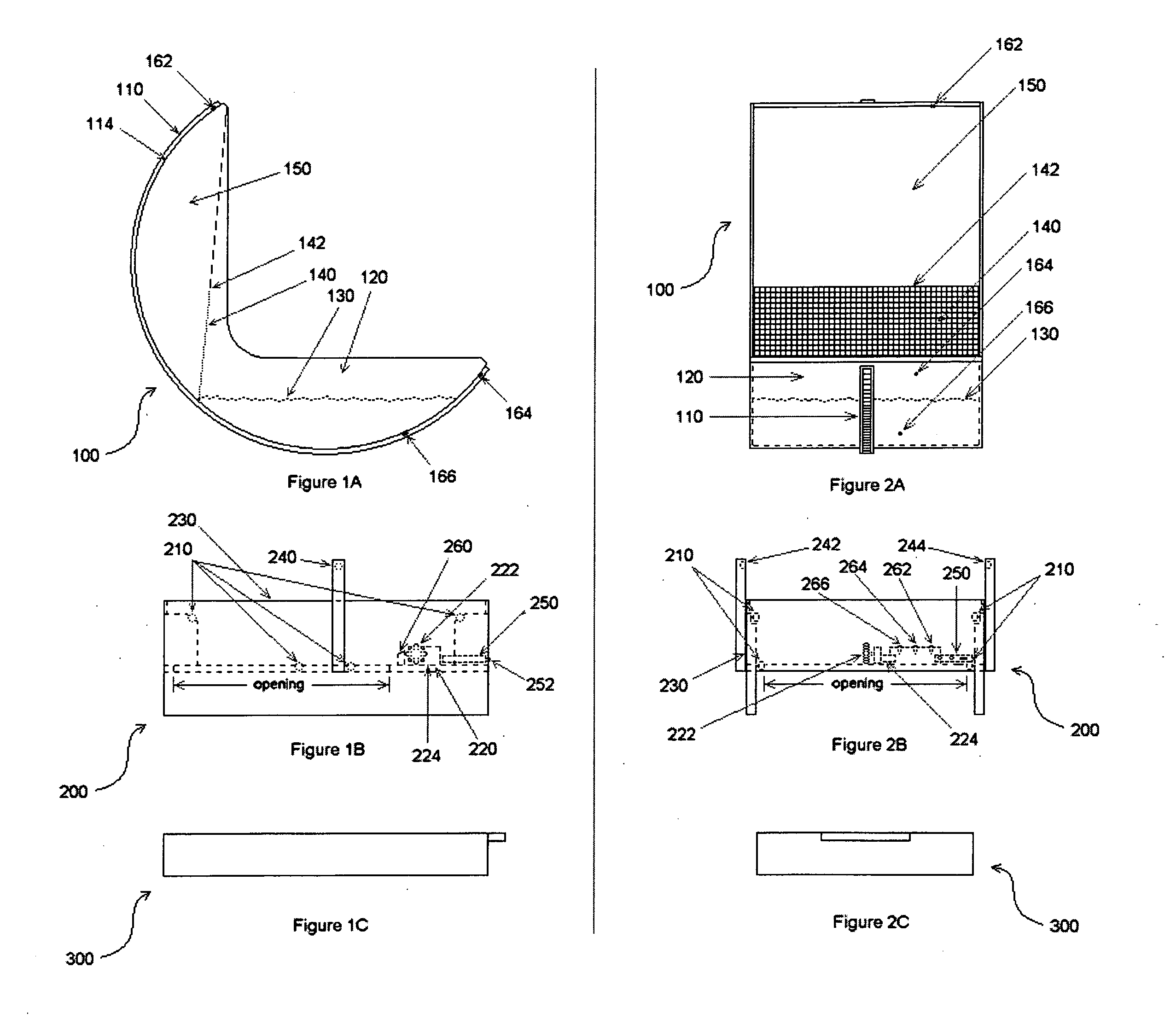
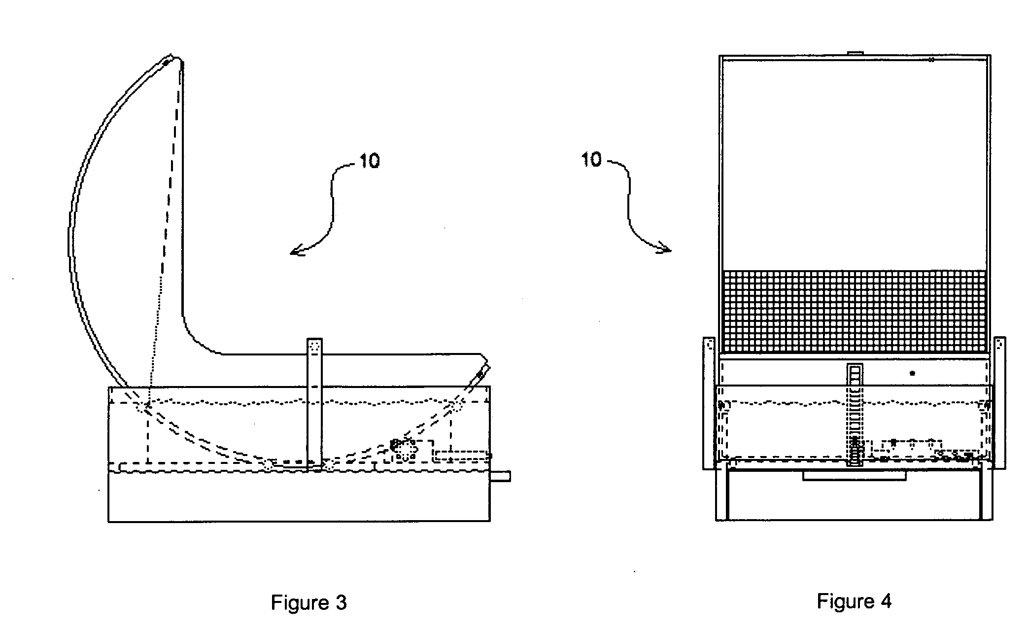
[0074] With reference to FIGS. 1-4, an embodiment of the instant invention 10 includes a First Unit Assembly 100, a Second Unit Assembly 200 and a Waste Receptacle 300. The Second Unit Assembly 200 provides a base that rests on a floor, counter, or other flat surface that is accessible by one or more pets, such as a cat or cats. The First Unit Assembly 100 rests on rollers 210 and a sprocket 222 of the Second Unit Assembly 200, and is prevented from moving laterally by a track 110 on a common outer surface 114 of the First Unit Assembly 100 and sidewalls 230 of Second Unit Assembly 200. A home position for the First Unit Assembly 100 is a position such that the top of the side walls 122 of the unenclosed litter compartment 120 are approximately parallel to the top of the sidewalls 230 of the Second Unit Assembly 200 and such that when litter 130 is placed in the unenclosed litter compartment 120, the litter 130 will rest at level state, as depicted in FIG. 3. When the First Unit Ass...


PUM


Abstract

A litter box has two unit assemblies and a waste receptacle. The first unit assembly has three components: an unenclosed litter compartment allowing animals' ingress and egress to / from the unenclosed compartment in one of multiple directions to deposit waste material; a compartment to temporarily hold filtered litter; and a pivotally mounted and / or flexible screen that filters out waste material from the litter that is being communicated away from the unenclosed litter compartment and toward the temporary compartment. The second unit assembly is a support base that has a motor mounted on the support base that manipulates the first unit assembly, and contains a motion sensor and controller that actuates the motor. The waste receptacle is a rectangular, box-shaped container with an open top into which animal waste is deposited. When a controller associated with the device detects the presence of an animal through use of a motion sensor, a process is started whereby the controller waits for a predetermined amount of time to start a physical cycle. If the presence of an animal is detected again before the physical cycle starts, the process is aborted and restarted. Once the physical cycle is started, the first unit assembly is partially rotated by the motor. This rotation of the first unit assembly relative to the vector force of gravity causes the combination of litter and waste to move away from the unenclosed litter compartment, and toward the temporary compartment. The screen filters litter and waste being communicated toward the temporary receptacle, only allowing filtered litter to enter the temporary receptacle, and forcing waste solids to pass by the temporary compartment and into the waste receptacle. The motor then reverses, allowing the filtered litter in the temporary receptacle to be communicated back into the unenclosed litter compartment to its original location by passing through and under or back through the screen.

Description

PRIOR PROVISIONAL APPLICATION [0001] The present application claims the benefit of U.S. Provisional Application Ser. No. 60 / 728,426, filed Oct. 20, 2006, which is hereby incorporated by reference in its entirety.FIELD OF THE INVENTION [0002] The current invention relates to an apparatus and method for separating and removing animal waste material from litter, and in particular, to a technique that automatically removes cat waste material from litter in an unenclosed litter box. BACKGROUND OF THE INVENTION [0003] Many advances in technology related to automatic litter boxes have arisen to help improve the cleanliness of the litter box. One of the most significant advances is the use of what's called the “sifting method” of filtering litter. The sifting method has been employed by such devices as described in U.S. Pat. Nos. 4,846,104; 4,120,264; 5,507,252 and U.S. Pat. No. 5,662,066 (see also U.S. Pat. No. 6,463,881). The sifting method is significantly more effective than the so-call...

Claims


Application Information

Patent Timeline
IPC IPC(8): A01K1/035
CPCA01K1/0114
Inventor HORANOFF, JERRY
Owner AUTOMATED PET CARE PROD LLC
Learn More