Data driving circuits and organic light emitting displays using the same
- Summary
- Abstract
- Description
- Claims
- Application Information
AI Technical Summary
Benefits of technology
Problems solved by technology
Method used
Image
Examples
first embodiment
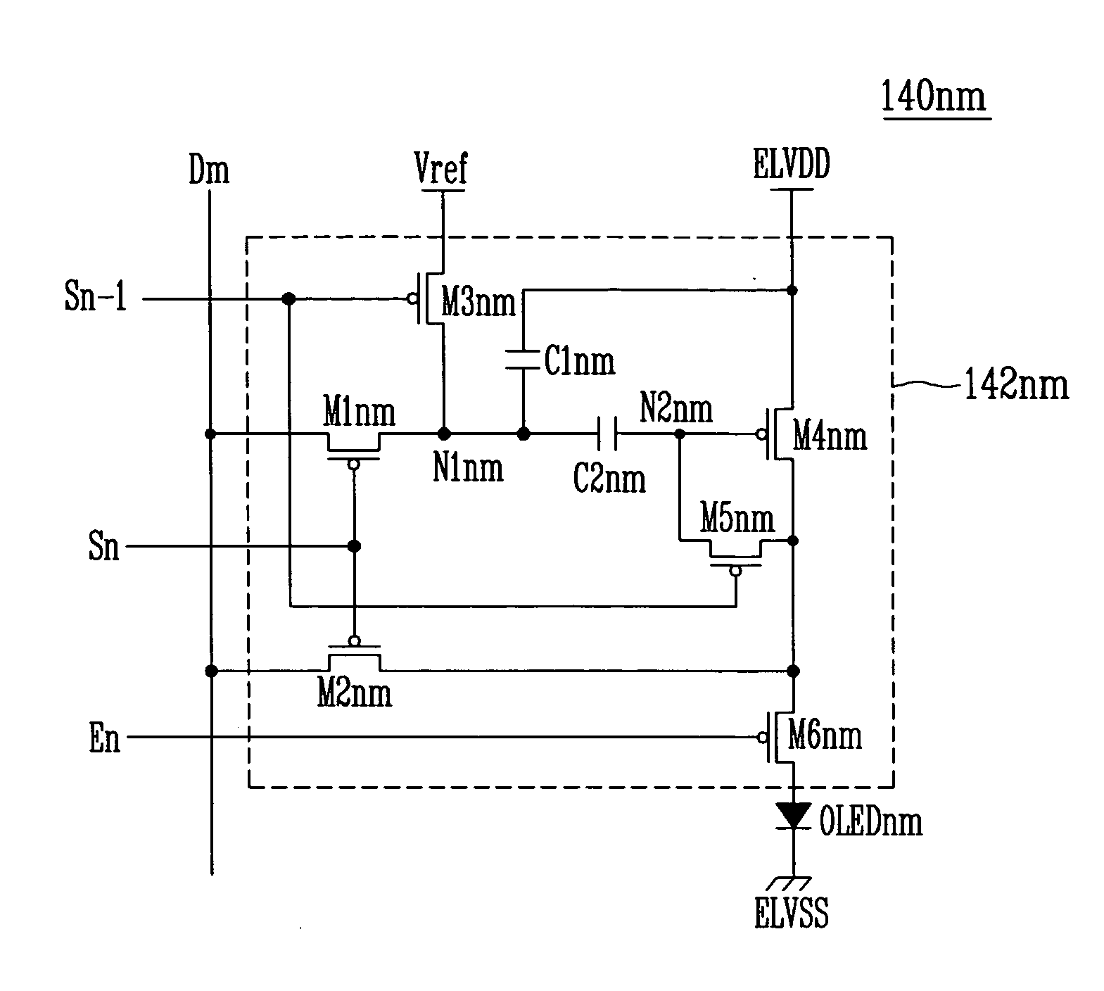
[0110]FIG. 9 illustrates a connection scheme for connecting the gamma voltage unit 300, the DAC 250j, the voltage controller 260j, the switching unit 290j and the current sink unit 280j shown in FIG. 6 and a pixel 140nj. For simplicity, FIG. 9 only illustrates one channel, i.e., the jth channel, and it is assumed that the data line Dj is connected to an nj-th pixel 140nj according to the exemplary embodiment of the pixel 140nm illustrated in FIG. 3.
[0111] As shown in FIG. 9, the gamma voltage unit 300 may include a plurality of distribution resistors R1 to R / . The distribution resistors R1 to R / may be disposed between the reference supply voltage Vref and the third supply voltage VSS′. The distribution resistors R1 to R / may distribute or divide a voltage supplied thereto. For example, the distribution resistors R1 to R / may distribute or divide a voltage between the reference supply voltage Vref and the third supply voltage VSS′, and may generate a plurality of gray scale voltages...
second embodiment
[0156]FIG. 12 illustrates a schematic diagram of a connection scheme connecting a gamma voltage unit 300, a digital-to-analog converter unit 250j, a switching unit 290j, a voltage controlling unit 260j and a current sink unit 280j illustrated in FIG. 6, and a pixel 140nj′, as illustrated in FIG. 5. For simplicity, FIG. 12 only illustrates one channel, i.e., the jth channel and it is assumed that the data line Dj is connected to the nj-th pixel 140nj′ according to the exemplary embodiment of the pixel 140nm′ illustrated in FIG. 5.
[0157] Methods for driving pixels 140 of a light emitting display will be described in detail with reference to FIGS. 10 and 12. First, when a scan signal SSn−1 is supplied to the n−1th scan line Sn−1, a voltage satisfying EQUATION 1 and EQUATION 2 may be applied to a first node N1nj′ and a second node N2nj′, respectively.
[0158] The n−th scan signal may be applied to the n−th scan line Sn. During the first period of a horizontal period 1H for driving the nj...
PUM
 Abstract
Description
Claims
Application Information
 - R&D
- Intellectual Property
- Life Sciences
- Materials
- Tech Scout
- Unparalleled Data Quality
- Higher Quality Content
- 60% Fewer Hallucinations
Browse by: Latest US Patents, China's latest patents, Technical Efficacy Thesaurus, Application Domain, Technology Topic, Popular Technical Reports.
© 2025 PatSnap. All rights reserved.Legal|Privacy policy|Modern Slavery Act Transparency Statement|Sitemap|About US| Contact US: help@patsnap.com


