
Portable electronic device

a portable electronic device and keyboard technology, applied in the field of electronic devices, can solve the problems of insufficiently accommodating larger keyboards such as qwerty and other well known keyboards, lack of multi-functional separate numeric keys, and ineffective increase in the effective user interface area provided by prior art “slide” phones

Active Publication Date: 2007-03-22
CONVERSANT WIRELESS LICENSING LTD
View PDF15 Cites 29 Cited by
  • Summary
  • Abstract
  • Description
  • Claims
  • Application Information

AI Technical Summary

Problems solved by technology

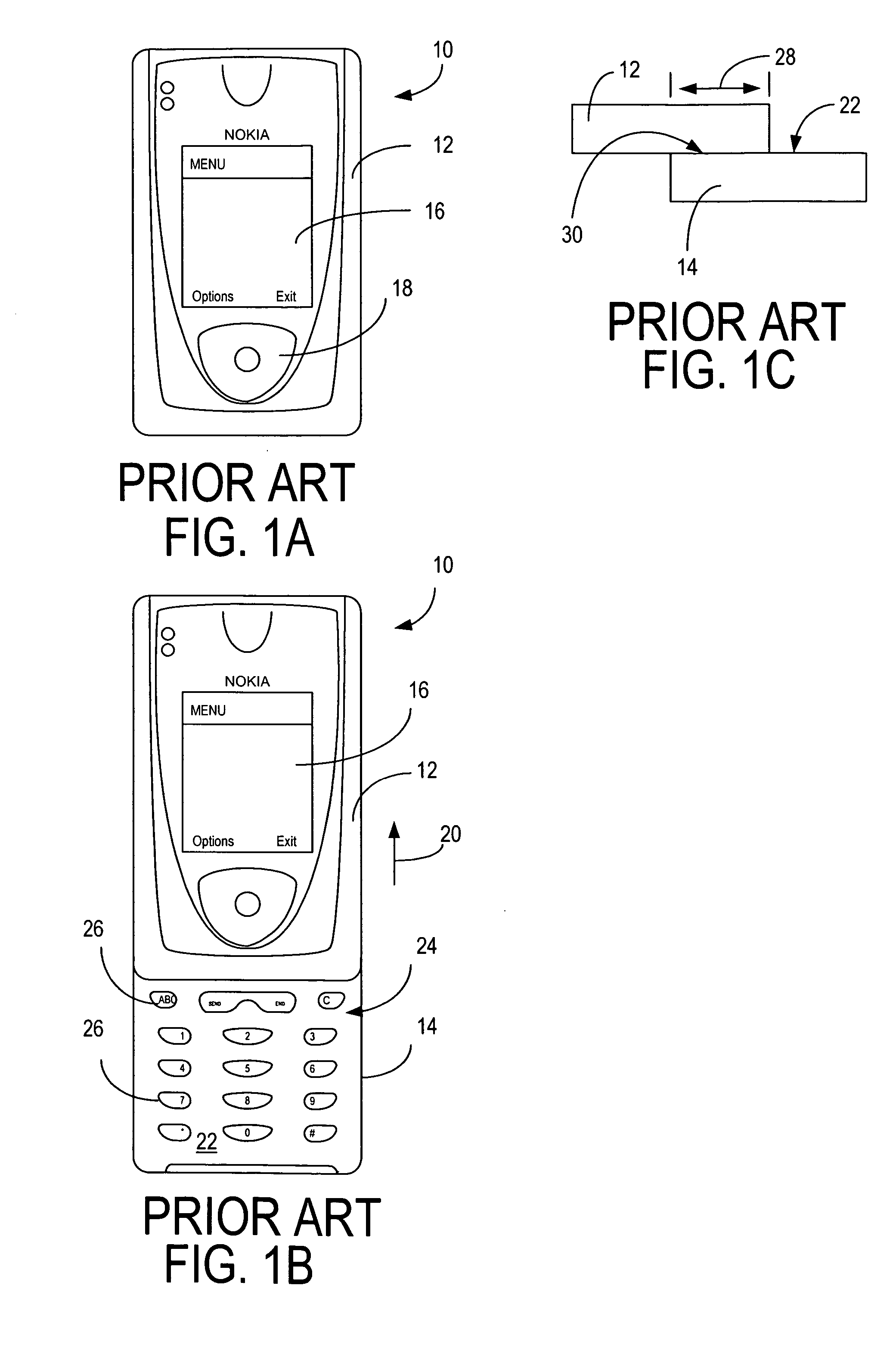
Although the “flip” phone enclosure configuration provides one method to expand the user interface surface and provide a larger screen display area while maintaining a relatively smaller size device enclosure compared to other mobile telephone devices wherein the user interface and the screen share a common surface area, it is not satisfactory to accommodate larger keyboards such as QWERTY and other well known keyboards.
Although such “slide” phones provide ease of usage in changing from one operative position to another operative position, the increase in effective user interface area provided by prior art “slide” phones is not as effective as “flip” phones because of the limited movement of the cover 12 with respect to the main body element 14.
Additionally, the prior art electronic device “flip” and “slide” enclosures such as described above lack a multi-functional separate numeric keypad which would be useful with a QWERTY keyboard and as a communication keypad for example in a mobile phone.

Method used


Image

  • Portable electronic device
  • Portable electronic device
  • Portable electronic device

Examples


Embodiment Construction

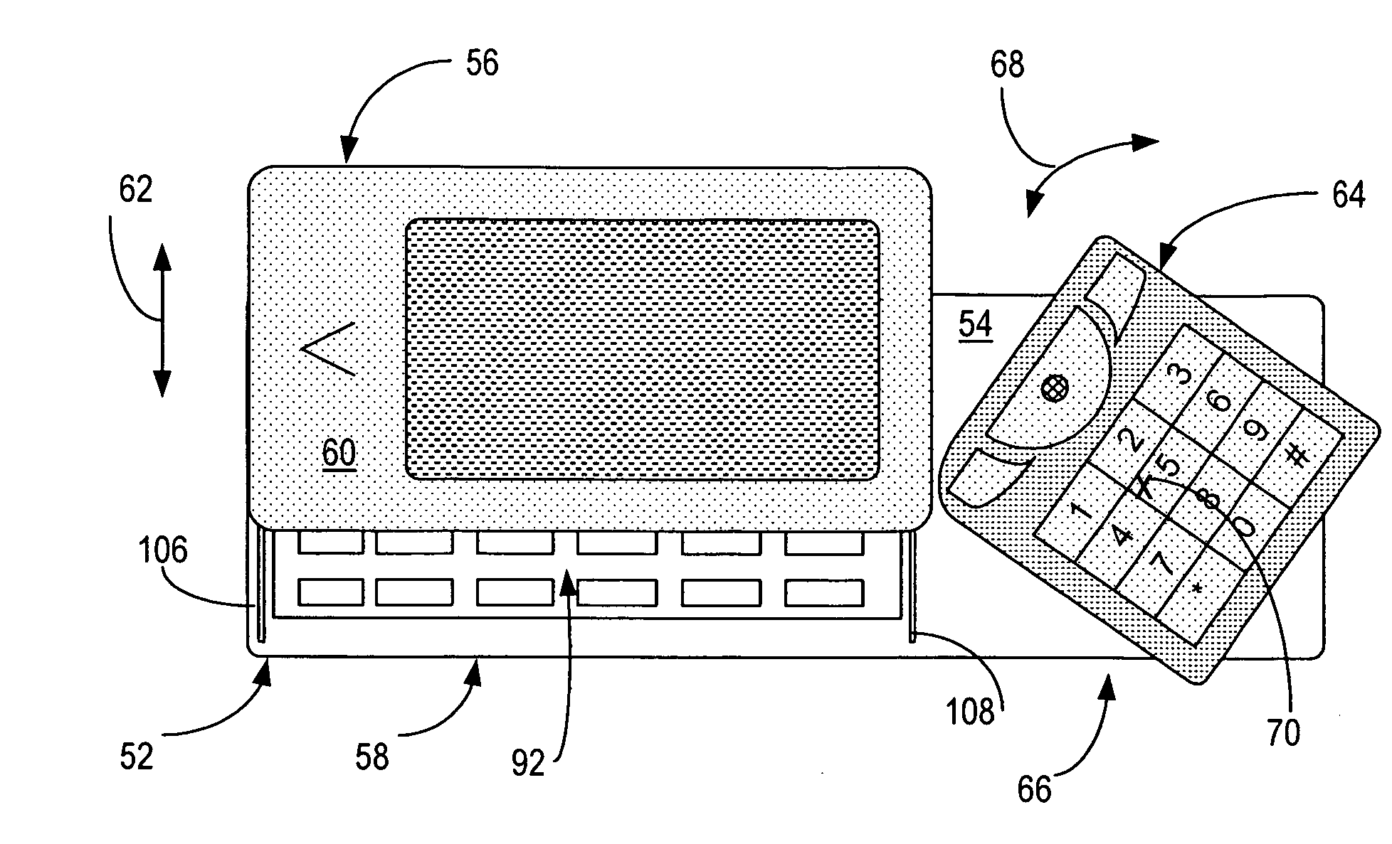
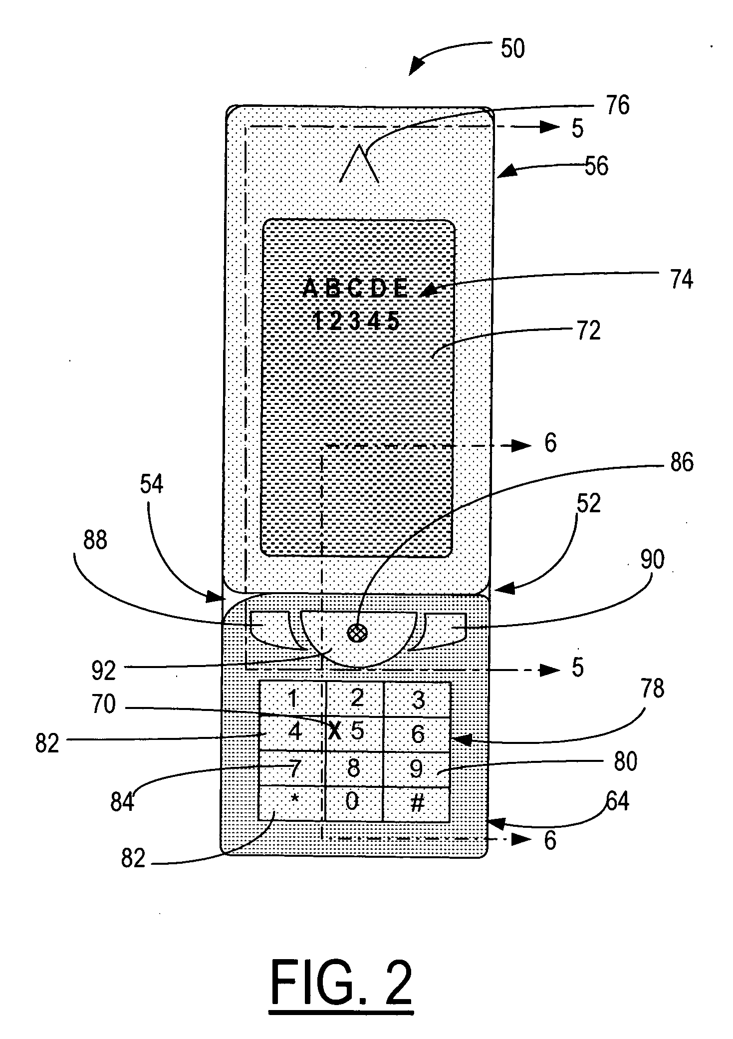
[0029] Turning now to the drawings and considering the invention in more detail and in particular with reference to FIGS. 2-6, a schematic front plan view of an electronic device embodying the present invention is illustrated schematically therein and shows for explanation purposes a mobile phone generally designated 50 in FIG. 2 in a closed first operative position. The mobile phone 50 includes a main body element 52 which has a major face surface 54. A second body element or panel generally designated 56 overlies at least one portion 58 of the main body element 52 and has a major surface 60 relative to usage. The second body element 56 is arranged for sliding engagement with the main body element 52 in a direction indicated by direction arrow 62 between the first operative closed position as illustrated in FIG. 2 and an open or second operative position as illustrated in FIG. 4. A third body element generally designated 64 overlies another portion generally designated 66 of main b...


PUM


Abstract

An electronic device with multiple body elements is configurable to predetermined fixed portrait and landscape orientations each of which define a respective different operative position. A first panel overlies at least one portion of a main body element first surface and has a surface relative to usage and is arranged for sliding engagement with the main body, whereby in a first fixed configuration at least one portion of the main body element first surface is covered and not available for usage and in the second fixed configuration said at least one portion of the main body element first surface is uncovered and available for usage. A second panel overlies another portion of the main body element first surface and is arranged for rotational movement on the main body element parallel to the plane of the main body element first surface, whereby in the first fixed configuration the second panel is in a first orientation and in positional alignment adjacent the first panel and in the second fixed configuration the second panel is rotated on the main body element to a second orientation and in positional alignment adjacent the at least one portion of the main body element first surface. The main body element may be constructed with an arrangement of keys to carry out an intended function such as a QWERTY keyboard. A display screen may be constructed in the second body element and a key arrangement may be constructed in the third body element to carry out an intended function.

Description

TECHNICAL FIELD [0001] The present invention relates generally to electronic devices, particularly portable electronic devices and more specifically to portable electronic devices having multiple body elements configurable to predetermined fixed orientations each of which define a respective different operative position. BACKGROUND OF THE INVENTION [0002] The demand by users and the purchasing public that portable electronic devices, particularly mobile telephone devices, become increasing smaller and lighter while at the same time providing an increasing number of different functions in addition to the basic telephone communication functions places a premium on available surface space for the user interfaces necessary to carryout the intended functions and operations of the associated features. In addition, there is also a demand for larger size screens for displaying images and text, for example, text messaging and word processing or other mobile applications utilizing keyboard en...

Claims


Application Information

Patent Timeline
IPC IPC(8): B41J29/02
CPCG06F1/1622G06F1/1624G06F1/1664G06F1/1671H04M1/72544G06F2200/1614H04M1/0231H04M1/0237H04M1/0247G06F1/1677H04M1/72427H04B1/38H04M1/02
Inventor KEMPPINEN, PASI
Owner CONVERSANT WIRELESS LICENSING LTD
Learn More