
Dual-mode camera

a dual-mode camera and camera body technology, applied in the field of cameras and sensors, can solve the problems of cell-to-cell non-uniformity, cell-to-cell non-uniformity, and the limitation of the dynamic range of the top end of such image sensors, so as to overcome the size and weight penalty

Inactive Publication Date: 2007-03-08
PR NEWSWIRE
View PDF3 Cites 36 Cited by
  • Summary
  • Abstract
  • Description
  • Claims
  • Application Information

AI Technical Summary

Benefits of technology

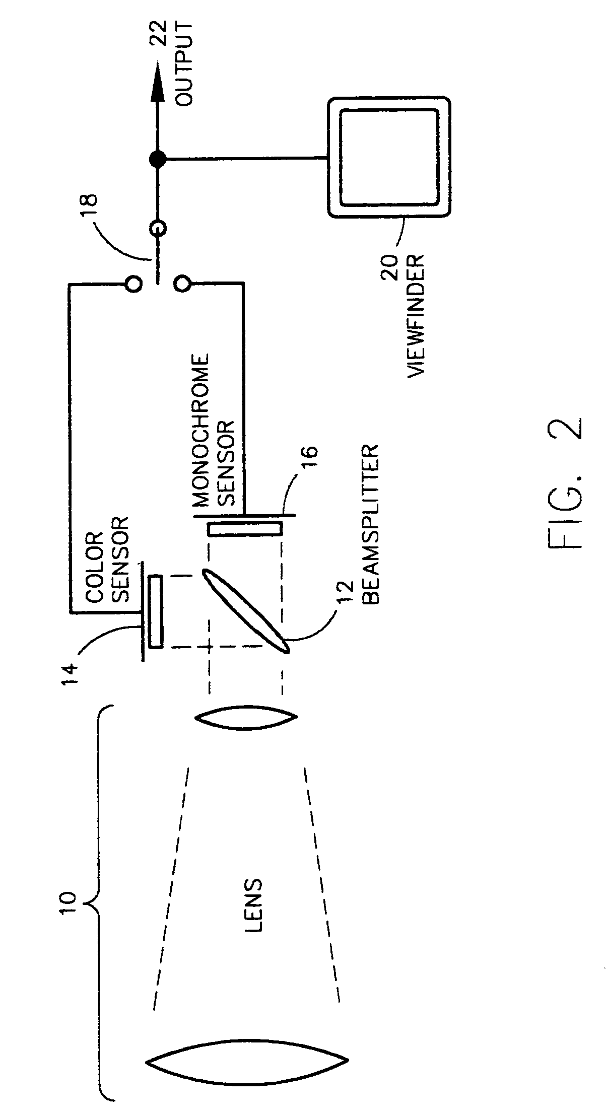
[0016] The subject invention is directed to a multi-imager camera, which is operable under extremes of illuminations, without the need for multiple optical paths. A single-lens system is employed, and a partially-reflective beamsplitting mirror is disposed to direct incoming images simultaneously to two or more sensors, respectively optimized for two different conditions, such as day / night operation or variable-zoom operation. This effectively overcomes the size and weight penalty incurred in a multiple-lens solution.

Problems solved by technology

The overall dynamic range of such image sensors is limited.
The top end of the dynamic range is limited by the cell's maximum-voltage capacity.
First, cell-to-cell nonuniformities exist in cell geometry, dark current, and sensitivity.
These nonuniformities result in a fixed-noise pattern superimposed on images produced by the camera, even in the presence of a uniform illuminant.
Second, thermal noise directly creates dynamic cell-to-cell voltage inequalities, which appear as ‘snow’ in rendered scenes.
These two sources of noise limit the ultimate sensitivity of the system at low levels of illumination, since the effective signal-to-noise ratio decreases as illumination decreases.
While this enhancement does provide the array with a means to render color imagery, it reduces the overall sensitivity of the array.
This reduction in optical sensitivity is due both to the non-ideal transmissivity of the filter to the desired wavelength, as well as to the elimination of energy at the remaining (non-desired) visible wavelengths.
While some progress has been made in improving the sensitivity of monochrome CCD imagers, such as the Watec 902H, the imagers remain insufficiently sensitive for moonlight or starlight operation.
Conventional CCD or CMOS imagers are unable to produce usable video under these conditions.
These image-intensifier devices have several operational limitations.
First, the devices may be damaged if operated at ‘normal’ illuminations, such as daylight.
Also, these image-intensifier devices are not capable of rendering color scenes and are thus used in monochrome systems only.
While this approach has utility, a significant weight and size penalty is incurred by the duplication of the lenses.
One deficiency is in the difficulty of establishing precise physical positioning of the mirrors after they have been moved.
This may be a serious deficiency if the system is used with a high magnification lens with a correspondingly small field of view, or if the system is used as a weapon sight.
Another deficiency of a moving-mirror system is the mere presence of moving parts, which inevitably reduces the ruggedness and reliability of the system.
A related problem entails the need for image stabilization within the camera.
Hand-held cameras are subject to the unavoidable vibration and tremors of the human hand.
This problem is exacerbated when long-range telephoto lenses are employed; the viewed image is increasingly unstable as the magnification is increased.
While useful, these approaches have their disadvantages.
This effectively reduces the overall resolution of the rendered image.

Method used


Image

  • Dual-mode camera
  • Dual-mode camera
  • Dual-mode camera

Examples


Embodiment Construction

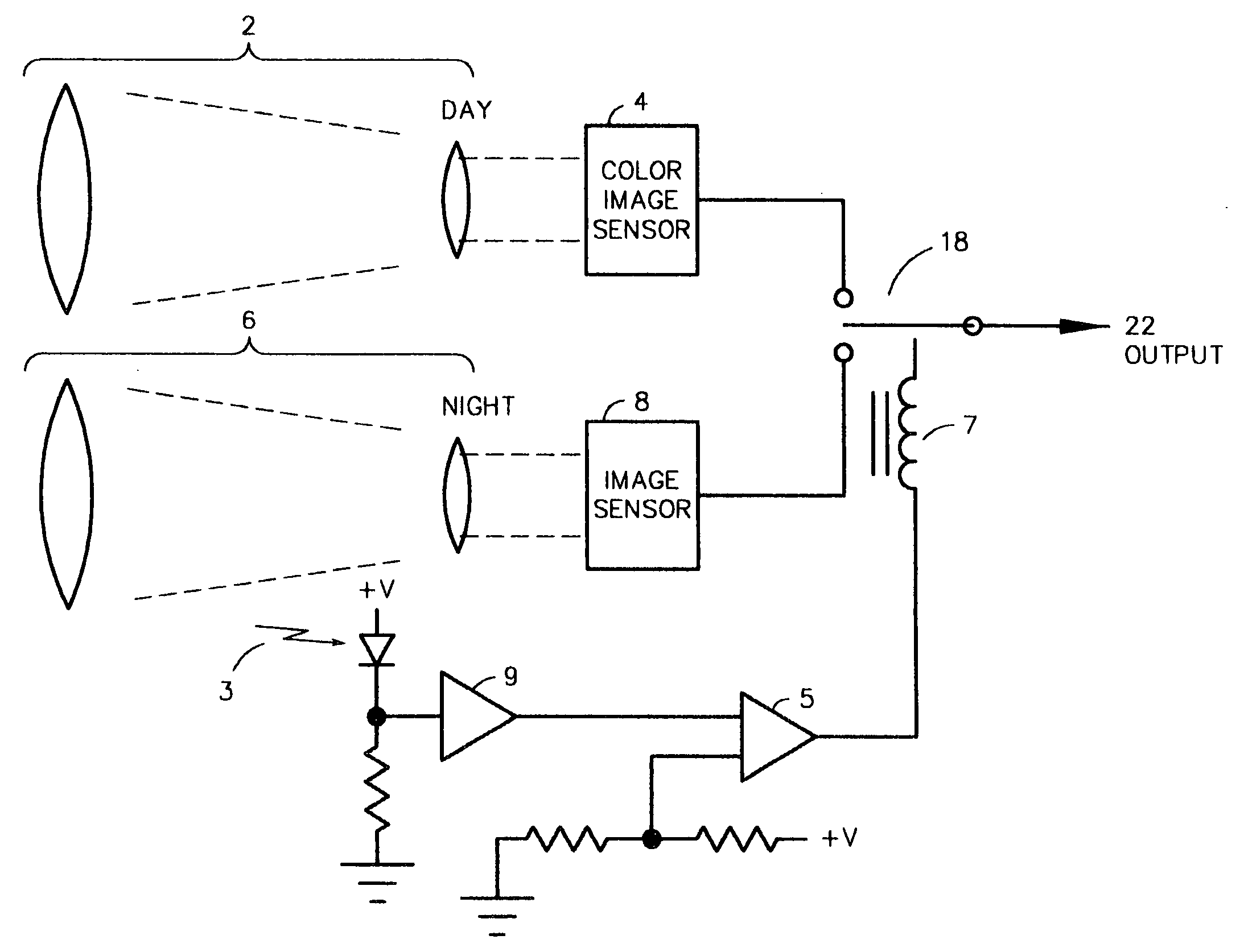
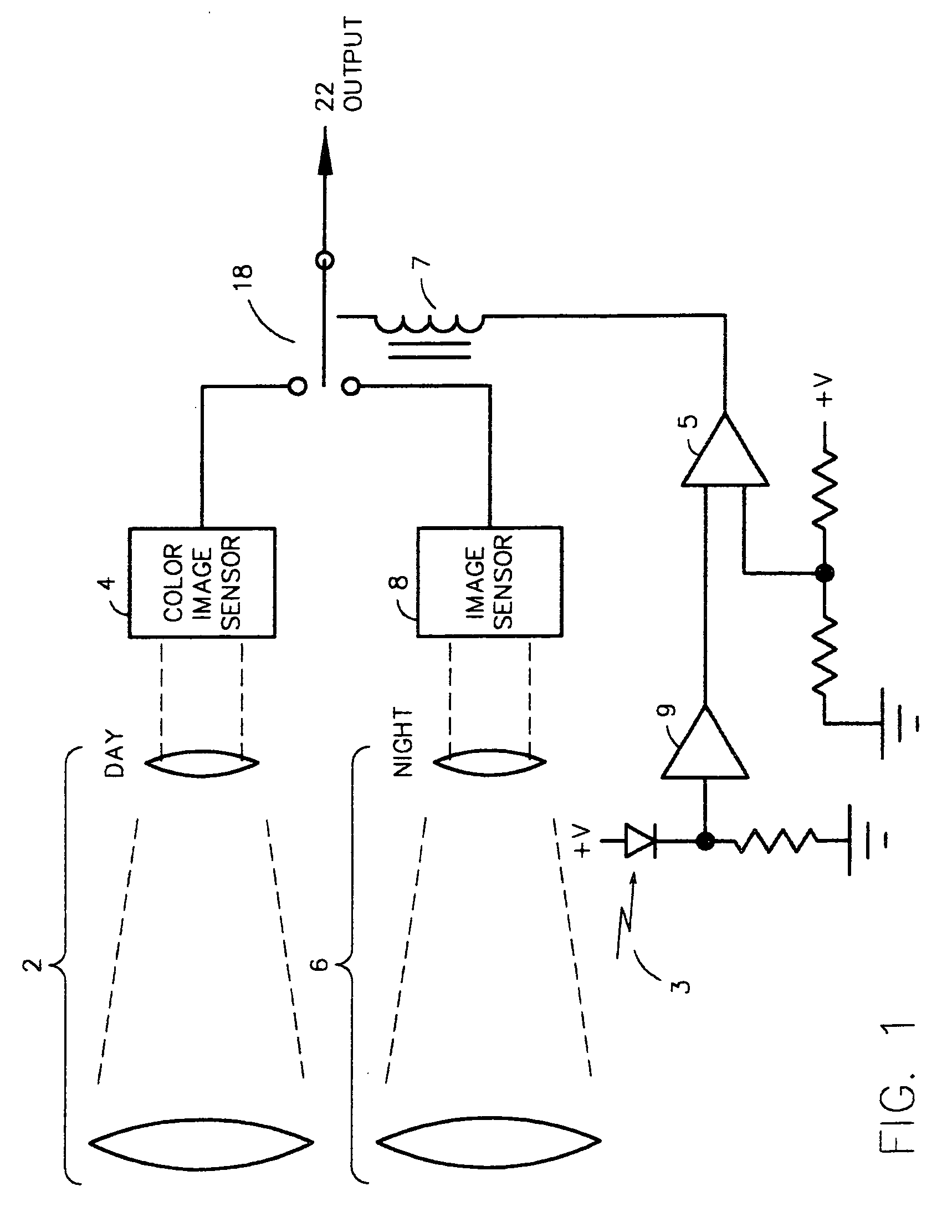
[0040] Referring now to FIG. 1, a prior-art system is depicted, which uses two lenses and sensors to span the desired range of ambient illumination. Daylight operation is accomplished using daylight lens 2 and color image sensor 4. Nighttime scenes are captured by lens 6 and image sensor 8, which is a monochrome area sensor optimized for high sensitivity. Typically, the overall ambient illumination is detected by, as an example, a photodiode 3. The resulting signal is buffered by buffer 9, compared with a reference value by comparator 5, and used to drive a video source selection relay 7.

[0041] The disadvantages of such a typical system are readily apparent. The overall size, weight and cost are dramatically increased by the inclusion of the additional lens.

[0042] An enhanced system, subject of the present invention, is depicted in FIG. 2. A single lens 10 is used to direct a desired scene onto the sensor optics, consisting of beamsplitting mirror 12, sensitive monochrome sensor 1...


PUM


Abstract

A dual camera system uses a single lens and no moving parts in the optical path. A single lens directs a desired scene to a partially reflective beamsplitting mirror, thence to a pair of image sensors. For day / night operation, one sensor may be optimized for nighttime sensitivity, while the other is optimized for daytime operation. Alternatively, one optical path may have greater magnification, thus allowing electronic zooming with no resolution loss. The system may be enhanced with an image intensifier for nighttime operation; digital sensors for improved resolution, or orthogonal gyroscopic accelerometers for image stabilization. Additionally, the monochrome and color images may be produced simultaneously and ‘fused’ algorithmically, yielding an improvement in sensitivity and color resolution compared with a conventional color camera.

Description

CROSS REFERENCE TO RELATED APPLICATIONS [0001] The present patent application is a divisional of, and claims the benefit of, patent application Ser. No. 09 / 593,901 filed on Jun. 14, 2000, titled “Dual-Mode Camera,” the entire contents of which are enclosed by reference here-in.BACKGROUND OF THE INVENTION [0002] 1. Field of the Invention [0003] The subject Invention is generally related to cameras and sensors and is specifically directed to a camera design that may use multiple imagers for day / night imaging, or for variable zoom. The design overcomes deficiencies of prior-art cameras wherein moving parts were required in the optical path, or wherein electronic zooming reduced image resolution. The cameras described may be either analog or digital. [0004] 2. Discussion of the Prior Art [0005] Video cameras have become commonplace in modern life. Improvements in process technology have resulted in cameras offering high performance at steadily decreasing prices. While early cameras univ...

Claims


Application Information

Patent Timeline
Patent Type & Authority Applications(United States)
IPC IPC(8): H04N5/232
CPCG02B13/16G03B17/16G03B17/48G03B19/22H04N5/23245H04N5/23248H04N2209/048H04N5/23296H04N5/238H04N5/33H04N5/332H04N9/045H04N5/23274H04N23/45H04N23/667H04N23/6842H04N23/68H04N23/69H04N23/75H04N23/11
Inventor MONROE, DAVID A.
Owner PR NEWSWIRE
Learn More