
Automatic brake control for hand-propelled vehicles

a technology for automatic brake control and hand-propelled vehicles, which is applied in the direction of hand cart accessories, hand cart accessories, carriage/perambulator accessories, etc., and can solve the problems of inability to apply brakes, often awkward actuation of hand carts, and injury of infants in prams or strollers

Inactive Publication Date: 2007-03-08
MARLOW JOHN KEITH
View PDF4 Cites 52 Cited by
  • Summary
  • Abstract
  • Description
  • Claims
  • Application Information

AI Technical Summary

Benefits of technology

[0013] The present invention thus provides in a further preferred aspect a hand-propelled vehicle of the type having a plurality of supporting wheels and a handle for propelling said vehicle, said vehicle including braking apparatus, said braking apparatus being adapted to prevent or stop movement of said vehicle upon a predetermined movement or velocity of said vehicle subsequent to release of said handle by a user.
[0014] Suitably, the handle includes touch sensitive means for sensing grip or touch on the handle or release of the handle. Pr...

Problems solved by technology

Many hand-propelled vehicles do not have brakes which means that for safety purposes they cannot be left unattended particularly on sloping ground.
In vehicles which do have brakes, the brake actuators for the brakes are either located adjacent the vehicle wheels such that actuation thereof is often awkward or alternatively brake actuators may be provided on the handle.
A disadvantage of both these arrangements is that if the brakes are applied and the user without releasing the brakes tries to push the vehicle, the vehicle can tip forwardly which in the case of prams or strollers may cause injury to an infant in the pram or stroller.
A disadvantage of these systems is that the brakes are always applied when the handle is released.
This may not be desirable in many situations.
In other systems, considerable gripping force is required to be applied to the movable handle portion to maintain the brakes in a released state which is inconvenient and tiring for the user.

Method used


Image

  • Automatic brake control for hand-propelled vehicles
  • Automatic brake control for hand-propelled vehicles
  • Automatic brake control for hand-propelled vehicles

Examples


Embodiment Construction

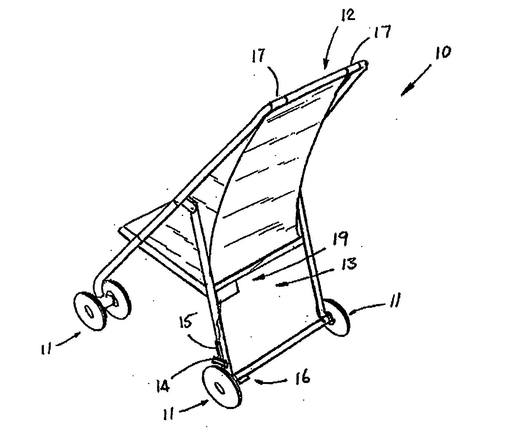
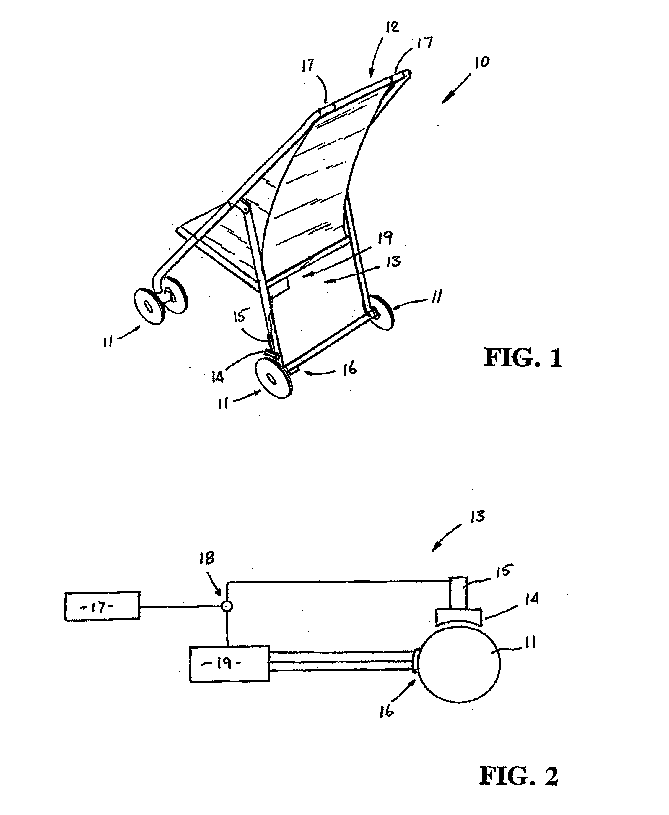
[0020] Referring to the drawings and firstly to FIG. 1, there is illustrated a hand-propelled vehicle 10 in this case in the form of a pram or stroller having a plurality of sets of supporting wheels 11, in this case four, and a handle 12 which may be gripped by a user for normally propelling and steering the vehicle 10. Arranged on the vehicle 10 is the braking apparatus 13 according to an embodiment of the invention (also shown in FIG. 2) including a braking member 14 such as a brake pad and actuating means 15 therefor for moving the braking member 14 towards and into engagement with a wheel 11 to effect braking thereof. The braking member 14 may engage the wheel 11 directly or a brake disc on or rotatable with the wheel 11. Alternatively, the braking member 14 may comprise a member which can cooperate with the wheel 11 in any suitable manner to prevent rotation thereof. The actuating means 15 for the brake suitably comprises an electrically operated actuating means such as a sole...


PUM


Abstract

Hand-propelled vehicle (10) such as a pram or stroller has electrically-operated brake apparatus (13) which is applied automatically on a user releasing their grip from handle (12). Braking does not occur immediately grip or touch sensors (17) on handle (12) register that the user has released handle (12). Programmable controller (19) is provided which only applies brake (13) if sensors (16) detect movement of vehicle (10) and / or that vehicle (10) has moved more than a set distance subsequent to release of handle (12). Therefore braking apparatus (13) acts as a safety feature that only applies if, say, a vehicle is released on a slope and movement due to the slope is detected.

Description

TECHNICAL FIELD [0001] This invention relates to improvements to hand-propelled vehicles. The present invention has particular application to prams or strollers for carrying babies or infants however the invention may be applied to any other form of hand propelled vehicle. BACKGROUND ART [0002] Hand-propelled vehicles of many different designs and configurations are known. Generally however, the vehicles are provided with a handle which is rearwardly disposed or rearwardly extending which can be grasped by the user so as to enable the vehicle to be propelled either forwardly or rearwardly and steered. Many hand-propelled vehicles do not have brakes which means that for safety purposes they cannot be left unattended particularly on sloping ground. In vehicles which do have brakes, the brake actuators for the brakes are either located adjacent the vehicle wheels such that actuation thereof is often awkward or alternatively brake actuators may be provided on the handle. A disadvantage ...

Claims


Application Information

Patent Timeline
IPC IPC(8): B62B9/08B60T7/12B60T7/14B62B5/04
CPCB60T7/12B60T7/14B62B5/04B62B5/0414B62B5/0476B62B5/048B62B5/0485B62B5/0452B62B2005/0471B62B9/08
Inventor MARLOW, JOHN KEITH
Owner MARLOW JOHN KEITH
Learn More