
Visualizing a complex network based on a set of objects of interest

a technology of complex networks and objects, applied in the field of network simulation, can solve problems such as the inability to see two devices at the same time, the inability to focus on particular components of the graph, and the inability to see two devices

Active Publication Date: 2007-02-22
RIVERBED TECH LLC +1
View PDF19 Cites 57 Cited by
  • Summary
  • Abstract
  • Description
  • Claims
  • Application Information

AI Technical Summary

Benefits of technology

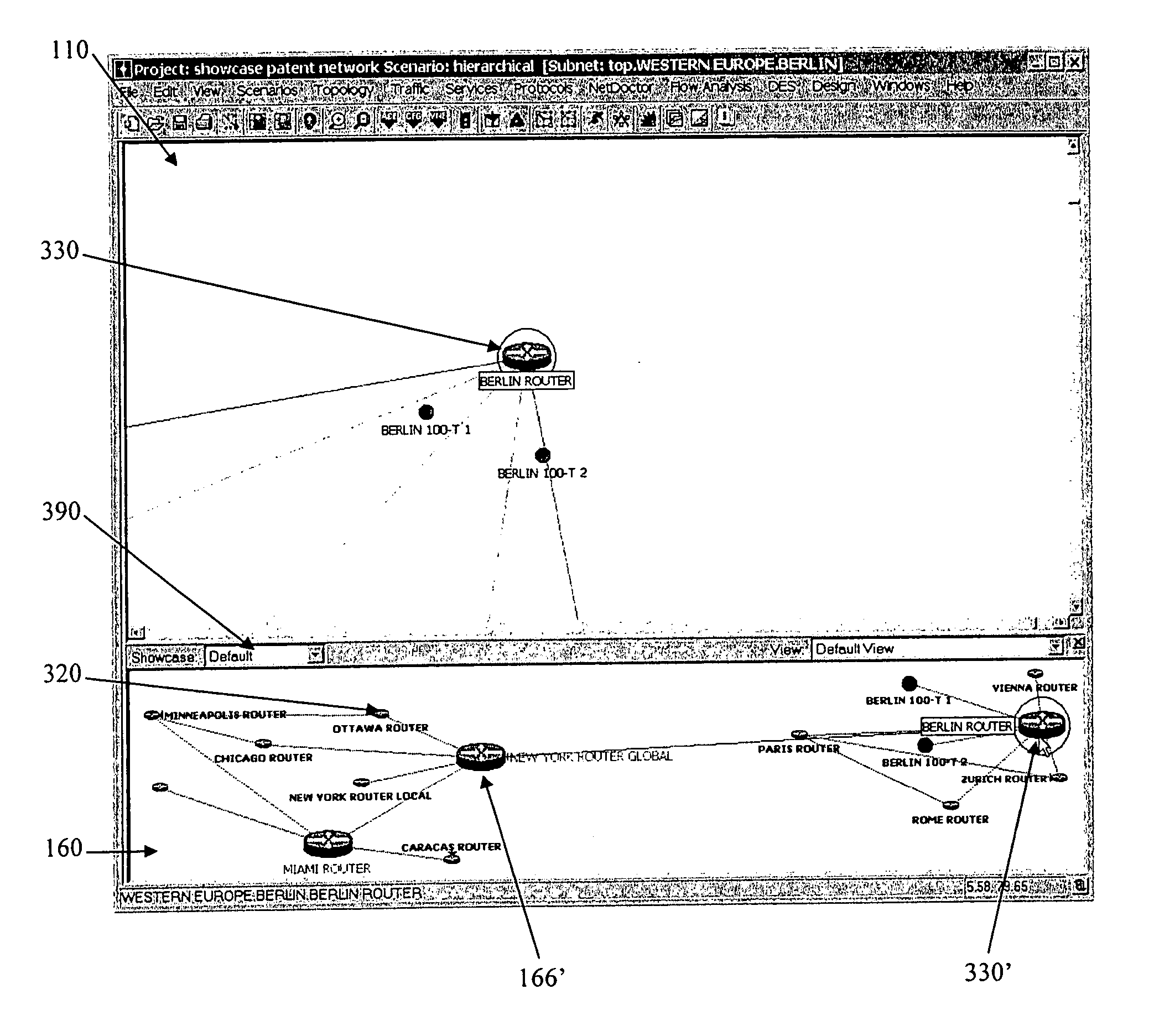
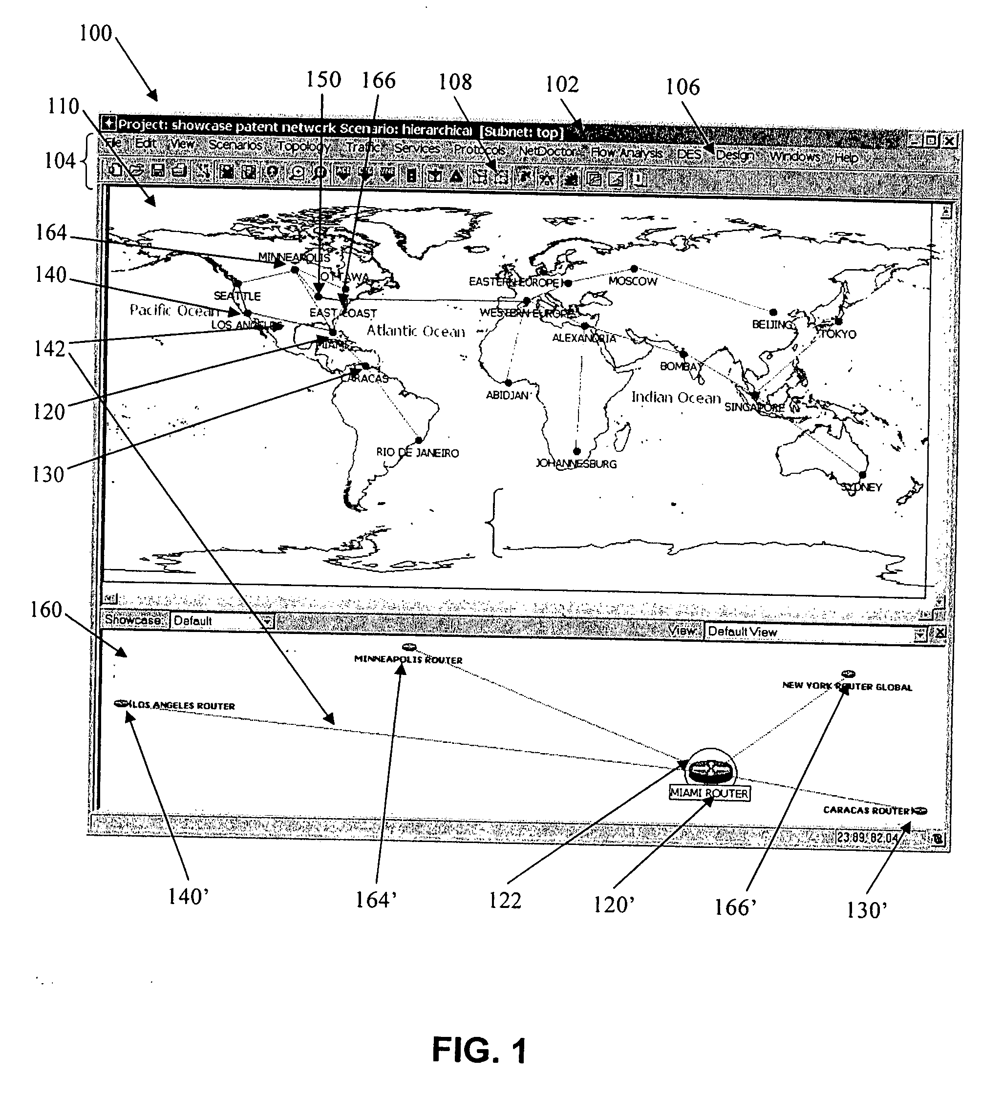
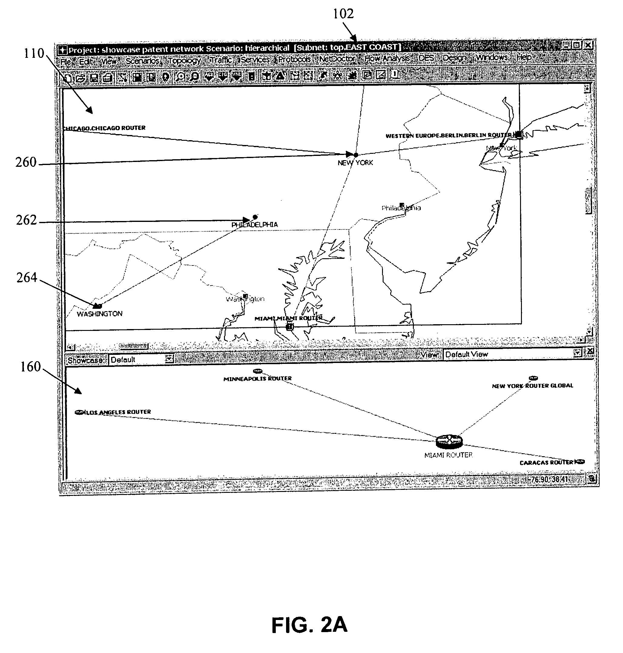
The present system is a system for displaying and interacting with a visual representation of a network of objects. The system includes a first region that displays a static representation of the network, which can be a single network sub-graph, and a second region that displays a dynamic representation of the network. The dynamic representation can show all of the network objects or a subset of them, and it can also show objects that are not fully connected in the static representation. The system allows users to easily view and interact with the network, making it easier to visualize and maintain.

Problems solved by technology

However, for larger networks, a common problem is that the scale and complexity of the visualization, such as a graph, make it difficult to focus on particular components within the graph.
However, to the extent that the hierarchy is statically defined, it will interfere with the simultaneous viewing of devices that happen to have different criteria values.
For example, if the hierarchy is based on proximity, it may not be possible to see two devices from different proximities at the same time.
Even in a flat network, without any hierarchy, it may be difficult to provide a focused view of devices on opposite ends of the visual representation because of all of the potentially intervening vertices and edges.
Either the user must zoom out to see everything at once, which may cause a lot of overlap in the visual representation, or the user must scroll the display window back and forth, which is cumbersome and may not enable a desired overview and comparison of the network and network components.
Further, even the reduced detail provided by the sub-graphs may obscure particular devices and / or interconnections of interest.
In addition, different portions of the graph of interest may not be selectable using fixed criteria, such as proximity conditions and given sub-graphs may not provide a desired level of context.
Finally, since the display region may be unscrollable, the original locations of the objects depicted in the second region may be too close together, even overlapping, or too far apart, leaving a lot of unused space.

Method used


Image

  • Visualizing a complex network based on a set of objects of interest
  • Visualizing a complex network based on a set of objects of interest
  • Visualizing a complex network based on a set of objects of interest

Examples


Embodiment Construction

[0024] The following are descriptions of illustrative embodiments that when taken in conjunction with the following drawings will demonstrate the above noted features and advantages, as well as further ones. In the following description, for purposes of explanation rather than limitation, specific details are set forth such as architecture, interfaces, techniques, etc., for illustration. However, it will be apparent to those of ordinary skill in the art that other embodiments that depart from these details would still be understood to be within the scope of the appended claims. Moreover, for the purpose of clarity, detailed descriptions of well-known devices, circuits, and methods are omitted so as not to obscure the description of the present system.

[0025] It should be expressly understood that the drawings are included for illustrative purposes and do not represent the scope of the present system. In the accompanying drawings, like reference numbers in different drawings designat...


PUM


Abstract

A user interface of a device for displaying a representation of a network of objects wherein a plurality of selectable objects are rendered, and each of the plurality of selectable objects are rendered having a given positioning relative to each other of the plurality of selectable objects. One or more edges are rendered interconnecting the plurality of selectable objects within a first region of the user interface. A second region is rendered in response to one or more of the selectable objects of the first region being selected. Objects corresponding to the selected objects are depicted in the second region while maintaining the given relative positioning. A number of additional objects may be retrieved from a database that indicates objects that are adjoining the corresponding objects. The adjoining objects are positioned in the second region and are interconnected to the corresponding objects by one or more additional edges.

Description

[0001] This application claims the benefit of U.S. Provisional Patent Application No. 60 / 709,724, filed Aug. 20, 2005.BACKGROUND AND SUMMARY OF THE INVENTION [0002] The present system relates to the field of network simulation and particularly to visualization of a computer network. [0003] Computers are today used extensively by users to implement many applications. Users interact through a user interface (UI) provided by an application running on the computer. The visual environment is displayed by the computer on a display device and the user is provided with an input device to influence events or images depicted on the display. UI's present visual images which describe various visual metaphors of an operating system, an application, etc. implemented on the computer. [0004] The user typically moves a user-controlled object, such as a cursor or pointer, across a computer screen and onto other displayed objects or screen regions, and then inputs a command to execute a given selectio...

Claims


Application Information

Patent Timeline
Patent Type & Authority Applications(United States)
IPC IPC(8): G06F9/00
CPCH04L41/145H04L41/22
Inventor MOLLITOR, ROBERT C.GUREVICH, YEVGENYNARAYANAN, VIVEKMALLOY, PATRICK J.
Owner RIVERBED TECH LLC
Learn More