Adaptive patient trigger threshold detection

a patient and trigger technology, applied in the field of patient respiratory care, can solve the problems of not automatically adjusting the trigger, current systems do not use standard pressure or flow triggers, and do not make these features selectable to the user

Inactive Publication Date: 2007-02-08
GENERAL ELECTRIC CO
View PDF10 Cites 44 Cited by
  • Summary
  • Abstract
  • Description
  • Claims
  • Application Information

AI Technical Summary

Benefits of technology

[0005] A method of adjusting a trigger threshold level of a patient ventilator comprising selecting an auto position on a trigger menu of the patient ventilator, receiving a set of unprocessed data into a sensor, calculating a set of patient data, calculating a control signal with the set of patient data, wherein the control signal reflects the trigger threshold level, and adjusting the trigger threshold level of the patient ventilator with the set of patient data. The method wherein the set of unprocessed data includes an expiratory flow component and an inspiratory flow component, wherein the set of unprocessed data is received by the sensor in a processor, and further wherein the processor calculates the set of patient data and the control signal. The method further comprising sending the set of patient data from the signal processing algorithm processor to a fuzzy logic control algorithm, wherein the fuzzy logic control algorithm executes the adjusting step with the set of patient data and further comprising displaying the set of patient data on a display device coupled to the patient ventilator. The method wherein the adjusting step adjusts the trigger threshold level to a finer level than can be achieved by a manual user interface and further comprising specifying a band wherein the auto position controls within the patient ventilator.
[0006] A system for adjusting a trigger threshold level of a patient ventilator comprising a trigger menu of the patient ventilator, wherein the trigger menu is set to an auto position, a sensor configured to receive a set of unprocessed data, a processor, coupl...

Problems solved by technology

Furthermore, current systems do not use standard pressure or flow triggers, and do not automatically adjust the trigger to the most sensitive level.
Current systems also do not make these features selectable to the user.

Method used


Image

  • Adaptive patient trigger threshold detection
  • Adaptive patient trigger threshold detection
  • Adaptive patient trigger threshold detection

Examples


Embodiment Construction

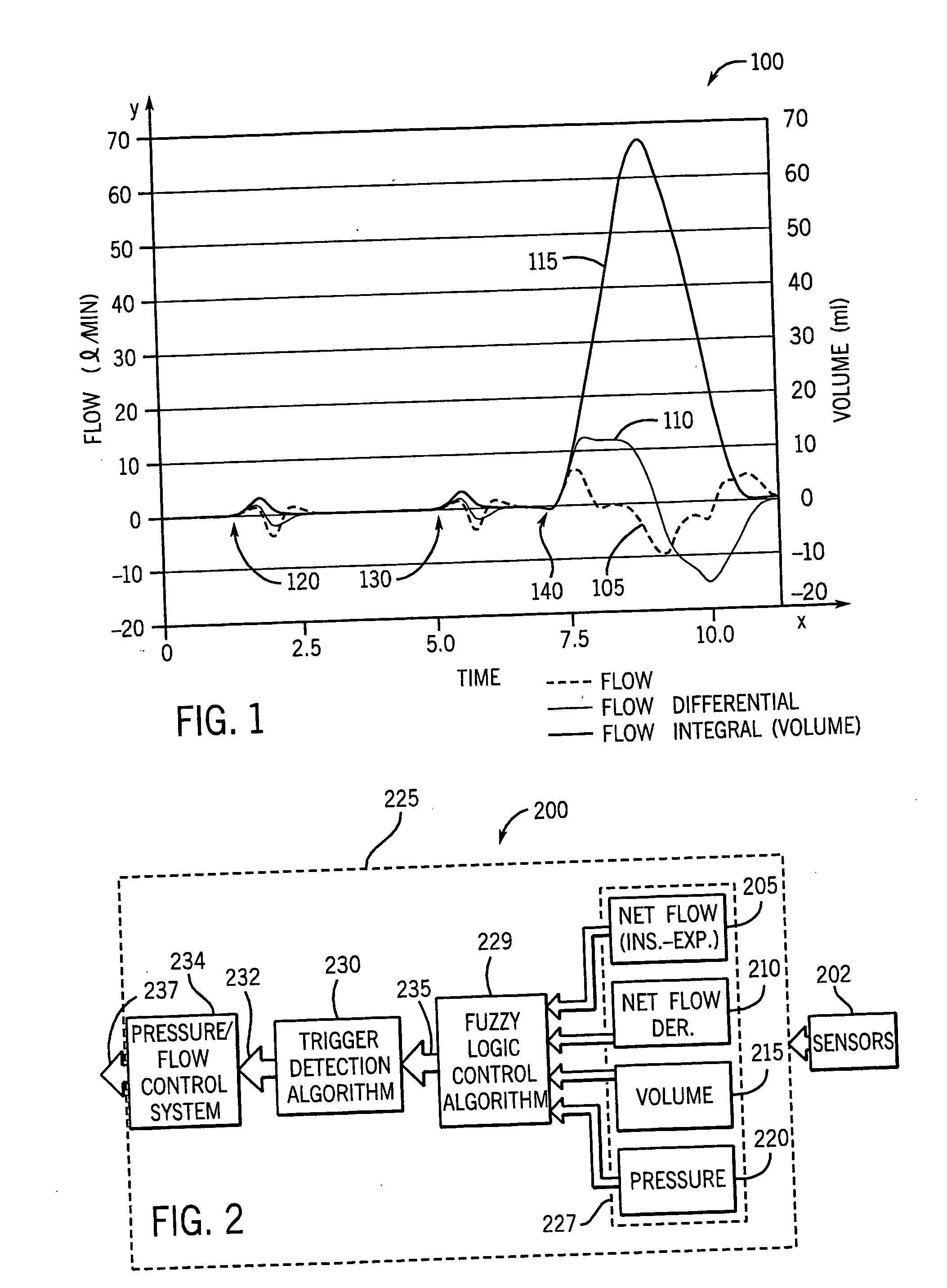
[0012]FIG. 1 depicts trigger characteristics 100 when the present invention is implemented. The graphical representation of trigger characteristics 100 includes a measure of amplitude in flow (liters per minute) and in volume (mL) along the y axis over a period of time in seconds along the x axis. The trigger characteristics 100 graphical representation of FIG. 1 includes graphical depictions for the flow response 105, flow differential response 110 and volume response 115. A first false trigger 120 and a second false trigger 130, precede the patient trigger 140, which will be discussed below.

[0013] Still referring to FIG. 1, the two very short pressure support breaths, the first false trigger 120 and the second false trigger 130, are initiated by auto-triggers followed by a breath caused by a patient trigger 140. Note how the times in which the flow response 105 is elevated are very short in the two false triggers 120, 130 that are auto triggered. In addition, flow differential re...


PUM


Abstract

The present invention is a method and system for adaptively detecting a patient trigger threshold. The system and method uses fuzzy-logic control algorithm to detect an appropriate trigger threshold by monitoring the number of patient triggers within a predetermined time frame. The system and method also detects an appropriated trigger threshold by monitoring the complete absence of false triggers over a predetermined time frame, increases in average flow, increases in pressure differential, and pressure drop, in order to lower the trigger threshold. The method and system of the present invention is selectable to the user, and adaptively changes the inspiratory trigger threshold.

Description

FIELD OF THE INVENTION [0001] This invention relates to the field of patient respiratory care. More particularly, the invention relates to the field of ventilator trigger sensitivity. BACKGROUND OF THE INVENTION [0002] Patient ventilators have certain modes that accommodate spontaneous, patient initiated breathing. When using these spontaneous modes, the clinician must select a threshold value for the type of trigger they have selected. This trigger threshold is compared to a flow or pressure value for example, to determine whether a patient is trying to start a breath on his or her own. Periodically the trigger level needs to be adjusted due to sensor drift, performance of procedure, changes in patient conditions, etc. [0003] Current systems, such as those disclosed in U.S. Pat. No. 6,626,175 to Jafari et al (hereinafter Jafari), do not adaptively change the inspiratory trigger threshold and the expiratory threshold. Rather, only the expiratory threshold. Furthermore, current syste...

Claims


Application Information

Patent Timeline
IPC IPC(8): A61M16/00
CPCA61M16/0051A61M2016/0021A61M2205/502A61M2016/0042A61M2016/0039A61M16/024
Inventor ACKER, JARON M.
Owner GENERAL ELECTRIC CO
Why Eureka
Try Eureka