
Multi-perf fracturing process

a multi-perf, fracturing technology, applied in the direction of drinking water installation, borehole/well accessories, construction, etc., can solve the problem of specialized charge arrangement while achieving a greater shot density, unable to penetrate as deeply into the surrounding formation as compared to traditional off-the-shelf guns, and prior art techniques

Inactive Publication Date: 2006-11-02
MATTHEWS H LEE
View PDF13 Cites 25 Cited by
  • Summary
  • Abstract
  • Description
  • Claims
  • Application Information

AI Technical Summary

Benefits of technology

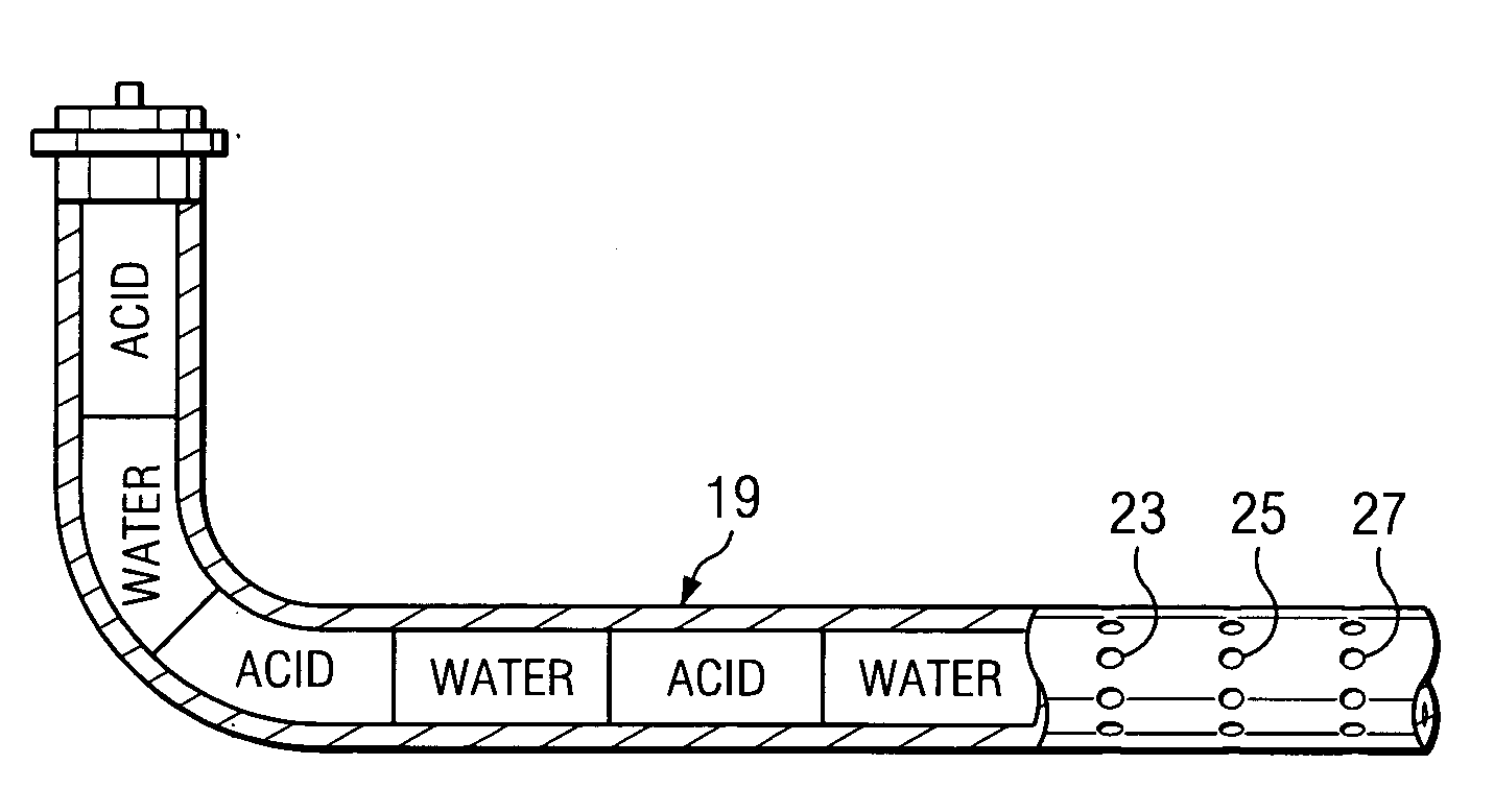
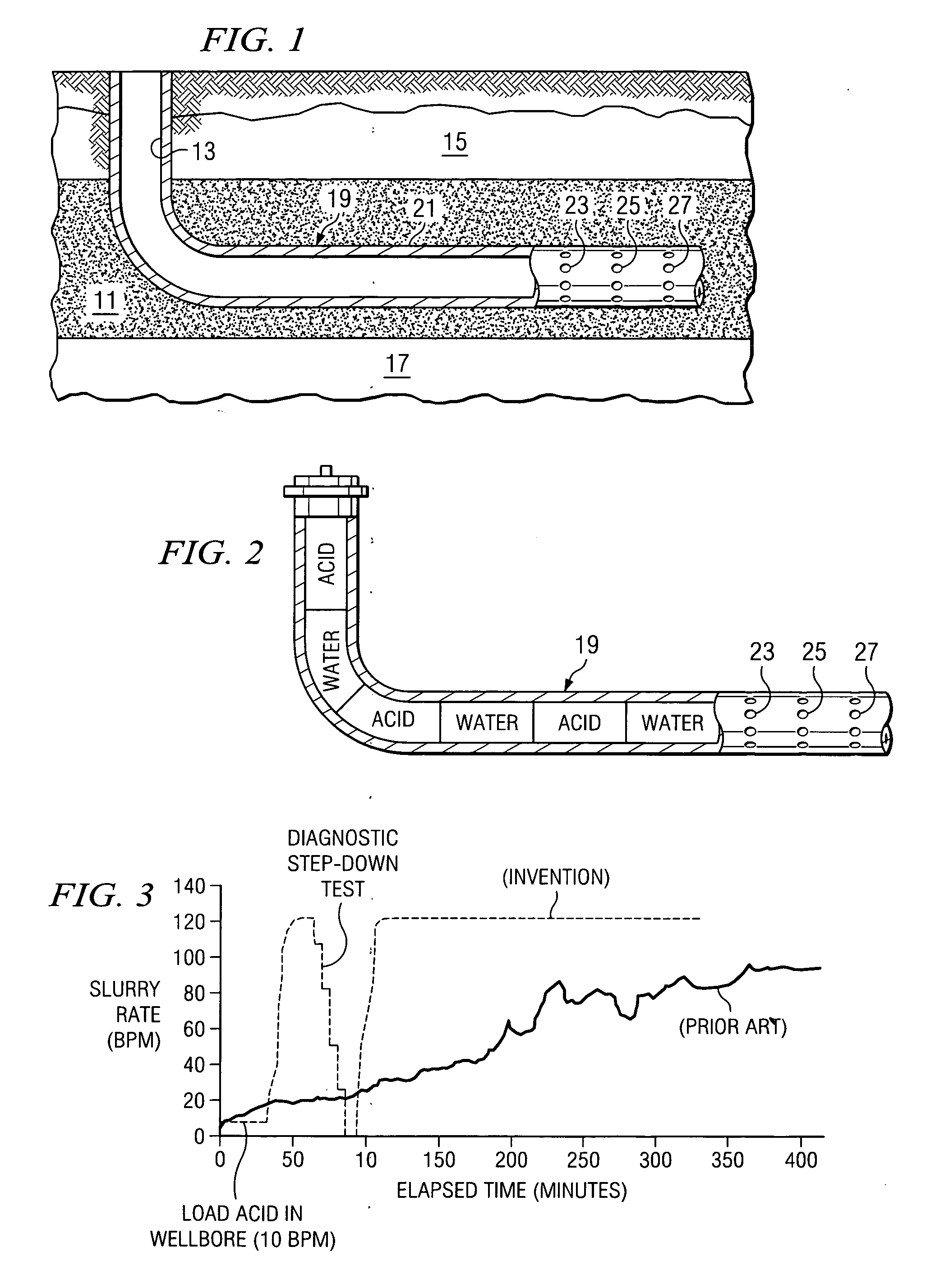
"The present invention combines various perforating and fracturing technologies to produce better results in drilling wells in hard, tight rock formations. The method involves forming multiple fractures in a subterranean formation from a deviated well bore using perforations in a predetermined number and size. The perforations are created at fracture initiation points in the well bore. Hydraulic pressure is applied to all the perforations simultaneously to extend the fractures in the formation in directions perpendicular to the deviated well bore. Propping agent can be deposited in the fractures to keep them open, and the fracture faces can be etched to form flow channels therein. The use of a tight perforating window is actually an advantage, as it allows for more efficient fracturing. The method also involves using a special pumping protocol to ensure even flow of fracturing fluid through each set of perforations. The combination of these techniques results in improved wellbore penetration and better fluid flow."

Problems solved by technology

One deficiency in the prior art techniques therefore involves the type of perforating technique employed.
However, none of these references, to Applicant's knowledge, teach the advantage of limiting the formation distance or interval being shot.
However, specialized charge arrangements while achieving a greater shot density, sometimes fail to penetrate as deeply into the surrounding formation as compared to traditional off the shelf guns.

Method used


Image

  • Multi-perf fracturing process
  • Multi-perf fracturing process
  • Multi-perf fracturing process

Examples


example

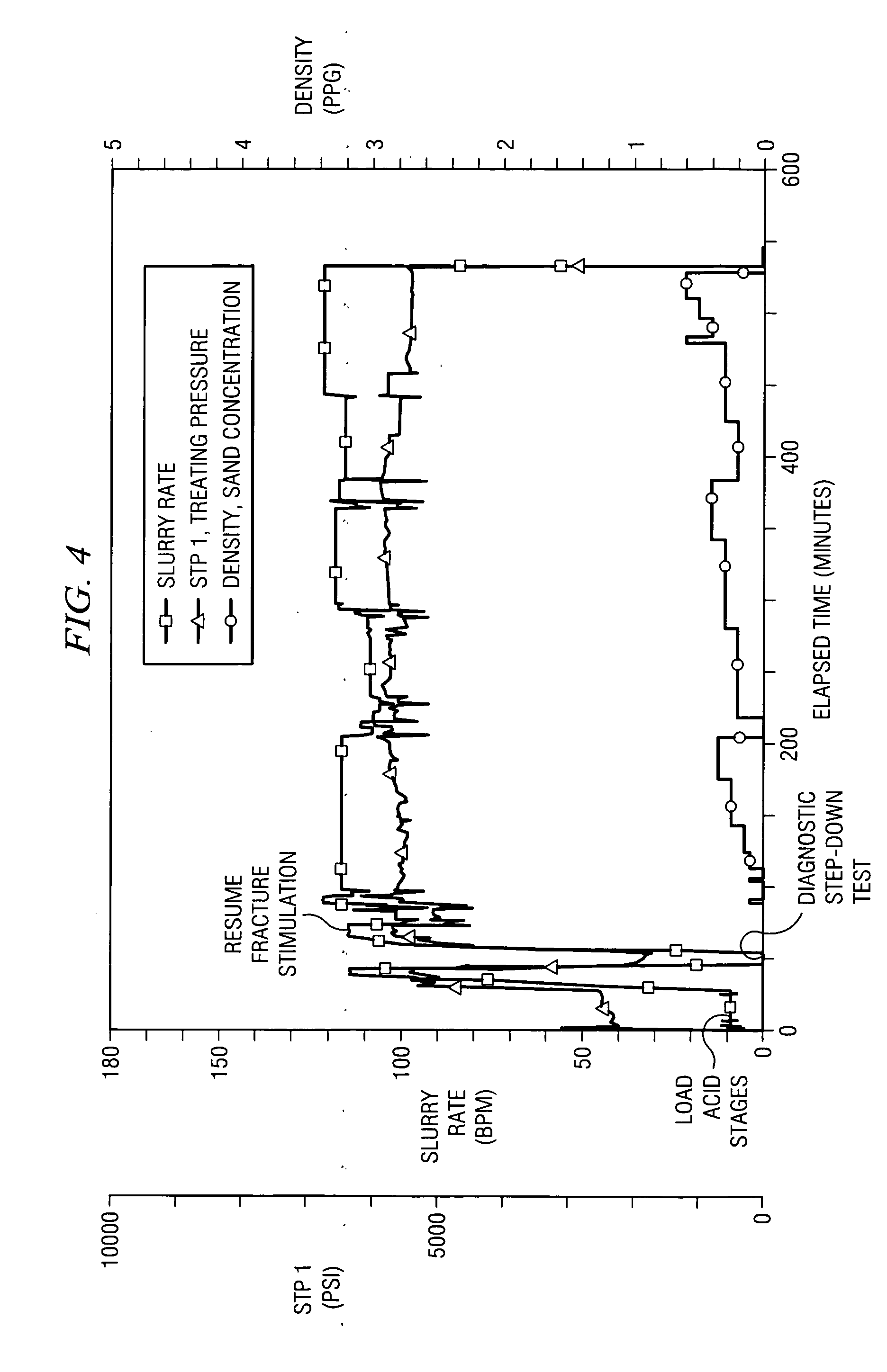
[0054] The subject well was drilled to 9414′ (MD) and completed with 67 joints 5½″ 17# N-80 BTC premium connections set from 9414′ (KB) to 6416′ and 146 joints 5½″ 17# N-80 LTC casing set from 6416′ to surface. A float collar (PBTD) is located at 9367′. The horizontal lateral was displaced with fresh water treated with biocide @ 0.4 gal / 1000 gals, 1000 gals of “Mud Clean III”, 10 bbls fresh water spacer, 2000 gals Sure-Bond and cemented with 345 sacks of lead slurry (Fort Worth Basin Premium+0.1% R-3) mixed at 13.0 ppg yielding 1.65 cu.ft. / sack followed by 695 sacks of tail slurry (Class “H”+0.25% R-3+0.25% FL-52+0.2% SMS) mixed at 14.4 ppg yielding 1.28 cu.ft / sack. The cement was displaced with the top plug and 217 bbls of treated water.

[0055] The casing string was milled and cleaned of cement and dope residue. The wellbore was then displaced with treated water spacer, gel swept and treated with biocide. The casing was then pressure tested to 6000 psi surface pressure with biocide...


PUM


Abstract

A method is shown for fracturing a subterranean formation from a deviated well bore. A plurality of spaced fracture initiation points are created in the well bore. Hydraulic pressure is applied to all of the sets of perforations at the fracture initiation points to extend a plurality of spaced fractures in the formation in directions substantially perpendicular to the deviated well bore direction. The same perforated interval in the wellbore is shot two or more times, using a conventional perforating gun in order to achieve a desired hole count over a shorter distance. The perforating technique is combined with a pumping protocol which better insures that the fracturing fluid being pumped flows more evenly through each set of perforations upon the application of hydraulic pressure rather than the majority of the fluid entering only the first perforated interval of the wellbore.

Description

CROSS REFERENCE TO RELATED APPLICATIONS [0001] The present invention claims priority from my earlier filed provisional application, Ser. No. 60 / 676,389, filed Apr. 29, 2005, entitled “Multi-Perf Fracturing Process.”BACKGROUND OF THE INVENTION [0002] 1. Field of the Invention [0003] The present invention relates in general to the completion of oil and gas wells and, in particular, to perforation and fracturing processes which are performed during completion operations. [0004] 2. Description of the Prior Art [0005] In drilling operations for the production of oil and gas deposits, operators strive to maximize both the rate of flow and the overall capacity of hydrocarbon from the subsurface formation to the surface where it can be recovered. Various stimulation techniques have been developed, one of the most commercially successful techniques being referred to as “hydraulic fracturing”. The rate of flow or production of hydrocarbon from a geologic formation is naturally dependent on nu...

Claims


Application Information

Patent Timeline
Patent Type & Authority Applications(United States)
IPC IPC(8): E21B43/11E21B43/26
CPCE21B43/263E21B43/11
Inventor MATTHEWS, H. LEE
Owner MATTHEWS H LEE
Learn More