
Method and apparatus for forming structural members

a structural member and contouring technology, applied in the field of structural member manufacture, can solve the problems of wrinkling of the plies, time-consuming manual layup process,

Active Publication Date: 2006-10-19
THE BOEING CO
View PDF28 Cites 132 Cited by
  • Summary
  • Abstract
  • Description
  • Claims
  • Application Information

AI Technical Summary

Benefits of technology

[0014] According to another method of the present invention, a charge is disposed on a die having first and second longitudinal portions, e.g., as a plurality of plies of a composite material. The portions are adjusted transversely so that the portions cooperatively define a recess. The charge is formed against the portions. Thereafter, while supported on the die, the charge is trimmed to a predetermined configuration of the structural member. The charge can be constrained to the die during forming so that both opposite surfaces of the charge are stressed in tension. Each portion can also be biased transversely inward during forming to control the adjustment of the portions. In addition, the portions of the die can be locked in position after forming to prevent transverse adjustment of the portions during trimming.

Problems solved by technology

However, such a manual layup process is time-consuming.
However, for thick laminates and complex shapes such as composite members defining C-, I-, or L-shaped beams, long flange lengths, contours along their length, variable thicknesses, joggles (or changes in direction), or offsets, vacuum bag drape forming can result in wrinkling of the plies.

Method used


Image

  • Method and apparatus for forming structural members
  • Method and apparatus for forming structural members
  • Method and apparatus for forming structural members

Examples


Embodiment Construction

[0038] The present invention now will be described more fully with reference to the accompanying drawings, in which some, but not all embodiments of the invention are shown. This invention may be embodied in many different forms and should not be construed as limited to the embodiments set forth. Like numbers refer to like elements throughout.

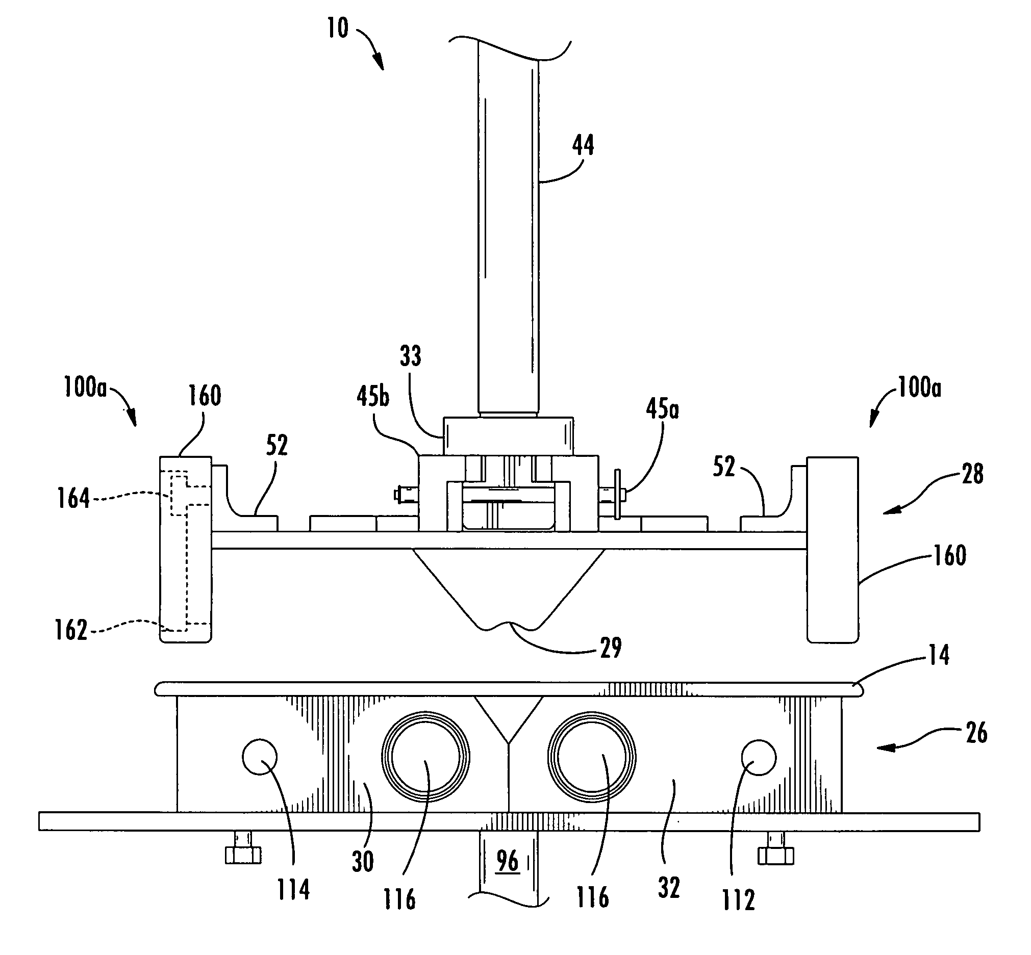
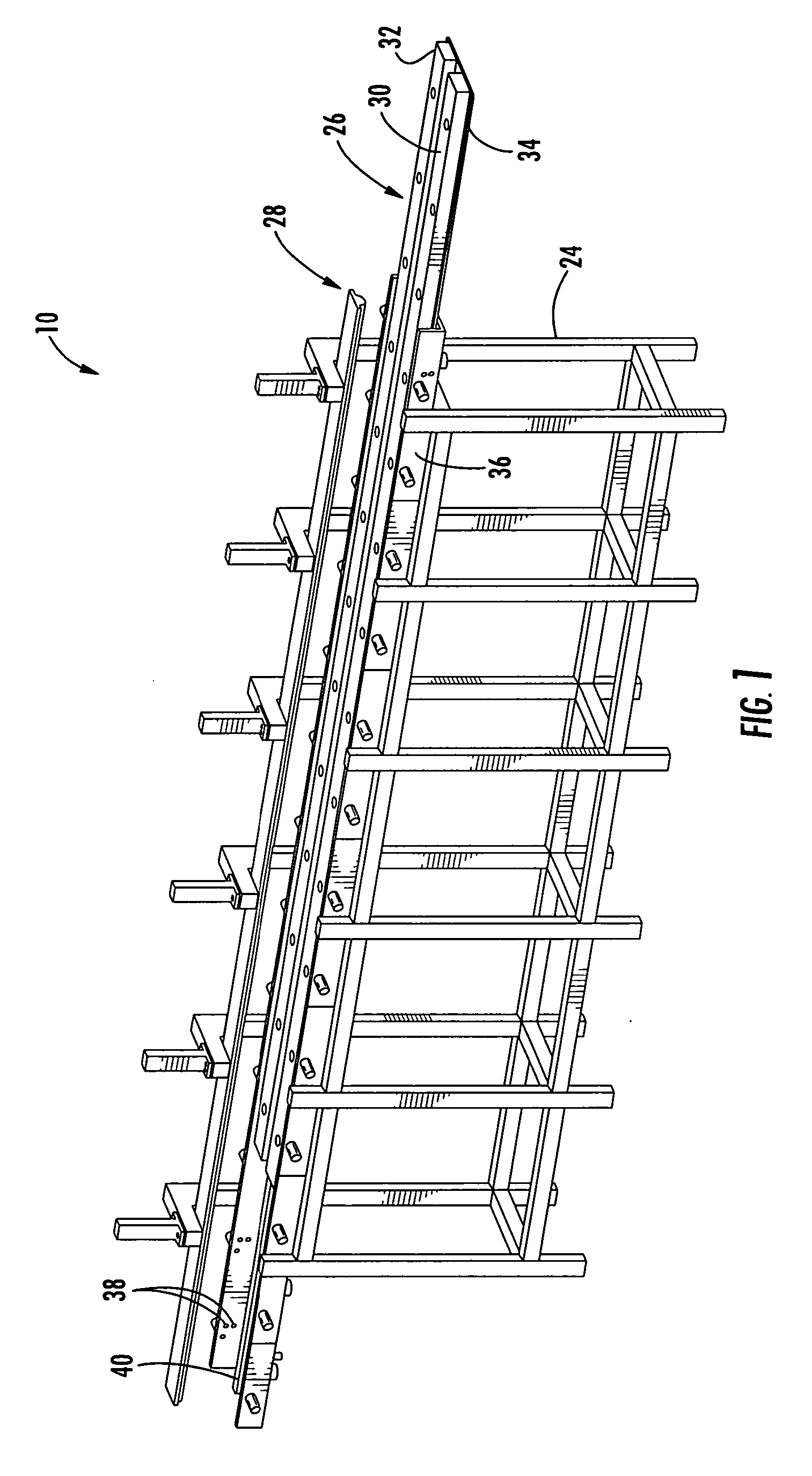
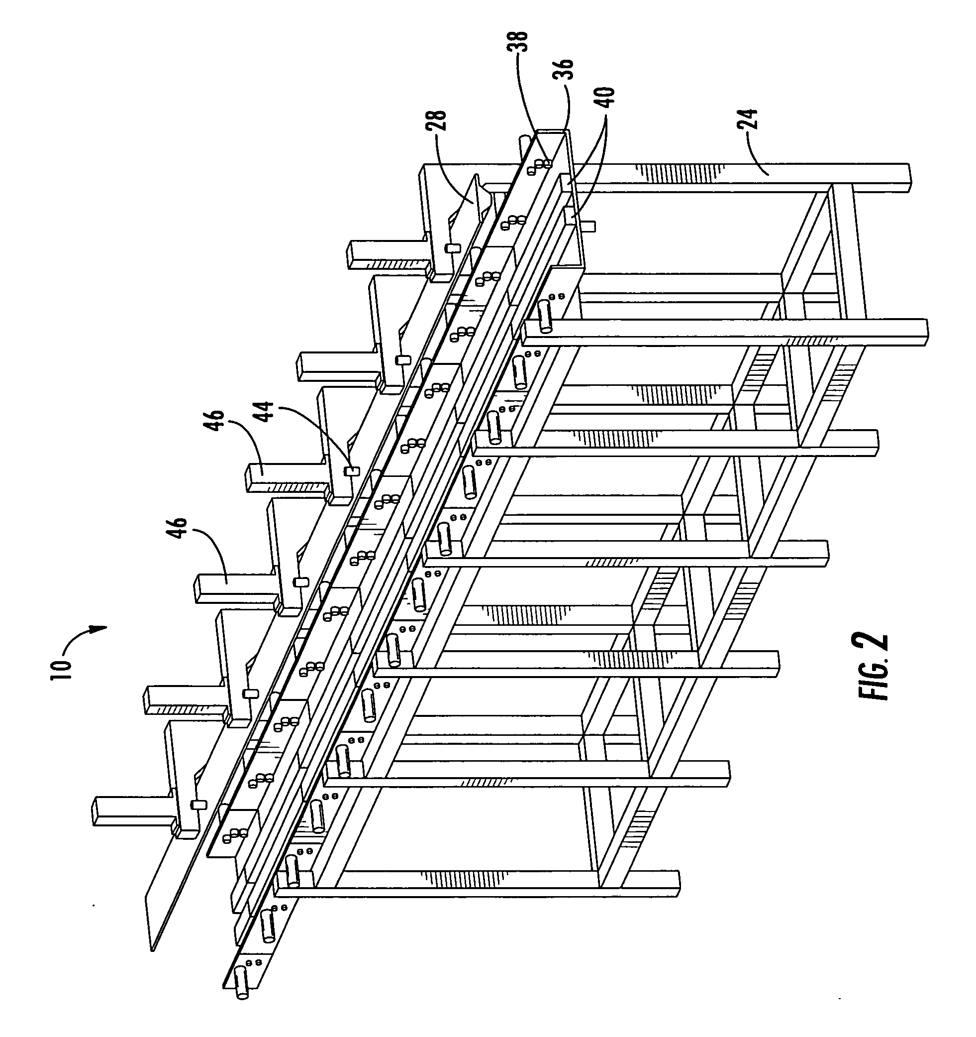
[0039] Referring now to the drawings, and in particular to FIGS. 1, 5, and 12, the apparatus 10 for forming structural members 12 according to one embodiment of the present invention can be used for forming structural members 12 of various sizes and configurations. The configuration shown in FIG. 12 and described throughout this description is a hat stringer for making a hat section stiffened composite. While shown as generally straight, the stringer may be curved or have complex curvature, as appropriate for the intended application. The structural members 12 are typically manufactured from a blank or charge 14. In particular, the charge 14 c...


PUM

PropertyMeasurementUnit
Linear densityaaaaaaaaaa
Electric chargeaaaaaaaaaa

Abstract

A method and associated apparatus for forming a composite structural member from a charge are provided. The charge can be disposed on a first die of the apparatus and formed to a desired configuration defined by a recess of the die by inserting a second die or a tool into the recess. In some cases, the first die can include two portions that are adjustable in a transverse direction so that the recess can be opened by the insertion of the second die or tool. The second die or tool can be a substantially rigid member or an inflatable bladder. In either case, the charge can be disposed on the first die, formed, and then further processed on the first die, thereby facilitating indexing of the charge for each operation.

Description

BACKGROUND OF THE INVENTION [0001] 1. Field of the Invention [0002] The present invention relates to the manufacture of structural members and, more particularly, relates to an apparatus and method for forming a contoured structural member. [0003] 2. Description of Related Art [0004] Composite members are commonly used in applications, such as aircraft and other vehicles, where light weight and high strength are desired or required. Often the composite members must be formed in a contoured configuration according to the particular application for the member. Complex contoured composite members are typically configured in a desired configuration while the composite material is in a “green” or uncured condition and then cured while supported in the desired configuration. One conventional method for forming such contoured composite members is by manually laying the composite materials onto a mandrel or other tool defining a male pattern corresponding to the desired configuration. For e...

Claims


Application Information

Patent Timeline
IPC IPC(8): B29C43/02
CPCB29C33/307B29C33/308B29L2031/008B29L2031/003B29C70/462B29D99/0007B29C70/545B29C2793/009B29C53/04B29C70/541Y02T50/40B29C39/12
Inventor LEE, MICHAEL A.WILLDEN, KURTIS S.JONES, DARRELL D.EVANS, RICHARD B.
Owner THE BOEING CO
Learn More