Femoral prosthesis component

a technology of femoral prosthesis and component, which is applied in the field of femoral prosthesis component, can solve the problems of difficult to remove the plug from the stem, high production cost, etc., and achieve the effect of easy removal of the proximal elemen

Inactive Publication Date: 2006-10-12
BENOIST GIRARD & CIE
View PDF6 Cites 18 Cited by
  • Summary
  • Abstract
  • Description
  • Claims
  • Application Information

AI Technical Summary

Benefits of technology

[0008] Thus, with this construction it is easy for the surgeon to slide the proximal element into place, and their tapered lengths allow the parts to wedge together, and it is also relatively easy to remove the proximal element if an alternative element is required by releasing the wedging action of the tapers.

Problems solved by technology

Such constructions are expensive to produce and it can be difficult to remove the plug from the stem once it has been placed in position.

Method used


Image

  • Femoral prosthesis component
  • Femoral prosthesis component
  • Femoral prosthesis component

Examples


Embodiment Construction

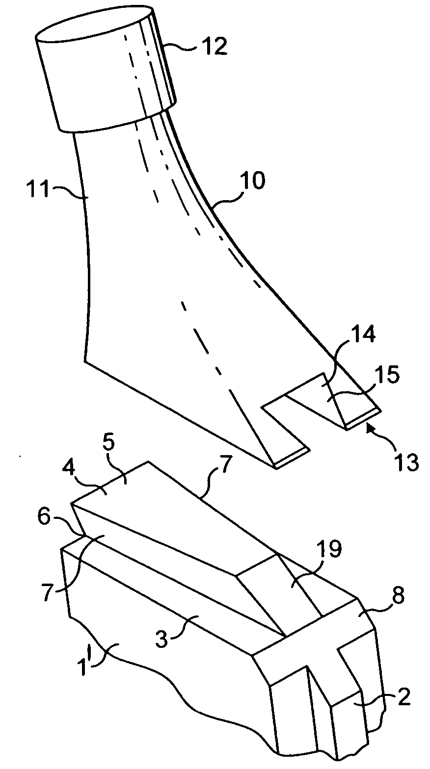
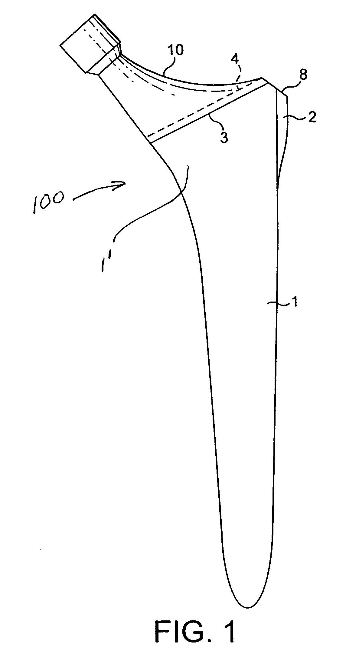
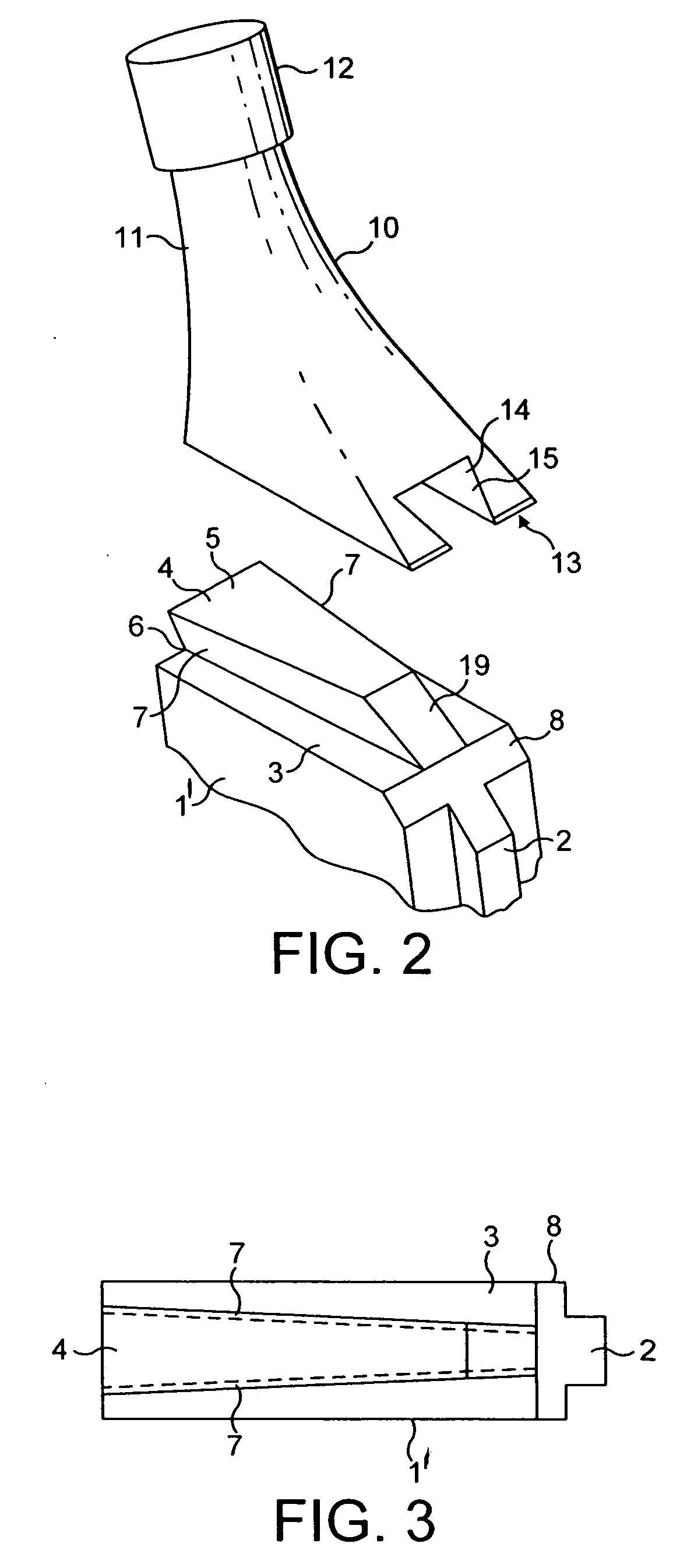
[0027] As shown in FIGS. 1 to 3 of the drawings a femoral prosthetic component of a replacement hip joint according to the present invention generally denoted as 100 comprises a distal stem 1 for fixing in a medullary cavity. The stem can be of any suitable size of shape and can be made from metal, for example a stainless steel or a composite synthetic material. In the preferred embodiment, a proximal end 1′ of the stem has a fin 2 on its lateral side to assist location.

[0028] The proximal end of the stem 1′ is shaped to provide a flat platform 3 on which is located a wedge-shaped undercut rail 4. The rail 4 tapers in width and depth from its medial to its lateral end and is undercut to that the cross-sectional width of his upper end surface 5 is greater than the cross-sectional width of its base 6 (along surface 3). The opposed side walls 7 of the rail are inclined to each other to provide a dovetail shape and rail 4 provides a tongue for a tongue and groove joint.

[0029] The uppe...


PUM


Abstract

A femoral prosthetic component of a replacement hip joint comprises a stem for fixing in a medullary cavity. A separate proximal element is provided with a neck for receiving a modular ball head or having an integral ball head. A dove tail-shaped system is provided for securing the proximal component to the stem which includes a sliding tongue and groove joint. The tongue being provided on the stem by an undercut rail which extends in a medial-lateral direction and the groove being provided in the separate proximal element. The tongue and groove being tapered along their lengths.

Description

BACKGROUND OF THE INVENTION [0001] This invention relates to a femoral prosthetic component for a replacement hip joint which comprises a stem for fixing in a medullary canal, separate proximal element provided with a neck to receive a ball head or having a ball head and connections, such as tapered connectors, for securing the proximal component to the stem which will enable a modular construction so that stems and heads of different sizes and / or shapes can be mated together. [0002] French Patents Nos. 2,626,168 and 2,721,200 both show femoral prosthetic components which have separate stems and proximal elements which can be fastened together but both constructions show the use of a tapered plug provided on the separate proximal element and which is located in a socket in the stem. Such constructions are expensive to produce and it can be difficult to remove the plug from the stem once it has been placed in position. [0003] U.S. Pat. No. 5,336,268 shows an adjustable hip joint endo...

Claims


Application Information

Patent Timeline
Patent Type & Authority Applications(United States)
IPC IPC(8): A61F2/36A61F2/00A61F2/30A61F2/46
CPCA61F2/36A61F2310/00179A61F2/367A61F2002/30172A61F2002/30332A61F2002/30383A61F2002/30385A61F2002/30387A61F2002/30507A61F2002/30604A61F2002/30797A61F2002/3611A61F2002/3625A61F2002/365A61F2002/3652A61F2002/3668A61F2002/4641A61F2002/4681A61F2220/0025A61F2220/0033A61F2230/0052A61F2310/00011A61F2310/00017A61F2/3609A61F2002/30884
Inventor BACHELIER, JEAN-CLAUDE
Owner BENOIST GIRARD & CIE
Why Eureka
Try Eureka