
Method and apparatus for washing a probe or the like using ultrasonic energy

a technology of ultrasonic energy and probe, which is applied in the direction of mechanical vibration separation, instruments, measurement devices, etc., can solve the problems of failure to disclose the structure of the combined probe tip/ultrasonic generator, the and the inability to carryover residual traces of a previously dispensed sample or reagen

Inactive Publication Date: 2006-08-17
BECKMAN COULTER INC
View PDF18 Cites 21 Cited by
  • Summary
  • Abstract
  • Description
  • Claims
  • Application Information

AI Technical Summary

Problems solved by technology

One problem associated with tools of this type is the carryover of residual traces of a previously dispensed sample or reagent to a container having another sample or reagent.
Carryover, particularly of fluid reagents and samples, results in poor quality and repeatability of the preparation and / or analysis operation.
However, the '491 patent merely expresses this desired end and fails to disclose any structure for the combined probe tip / ultrasonic generator.
Although the art has suggested combining a probe tip with an ultrasonic generator in a general manner for, inter alia, cleansing purposes, a workable use of ultrasonic energy to clean a probe or the like has not yet been found.

Method used


Image

  • Method and apparatus for washing a probe or the like using ultrasonic energy
  • Method and apparatus for washing a probe or the like using ultrasonic energy
  • Method and apparatus for washing a probe or the like using ultrasonic energy

Examples


Embodiment Construction

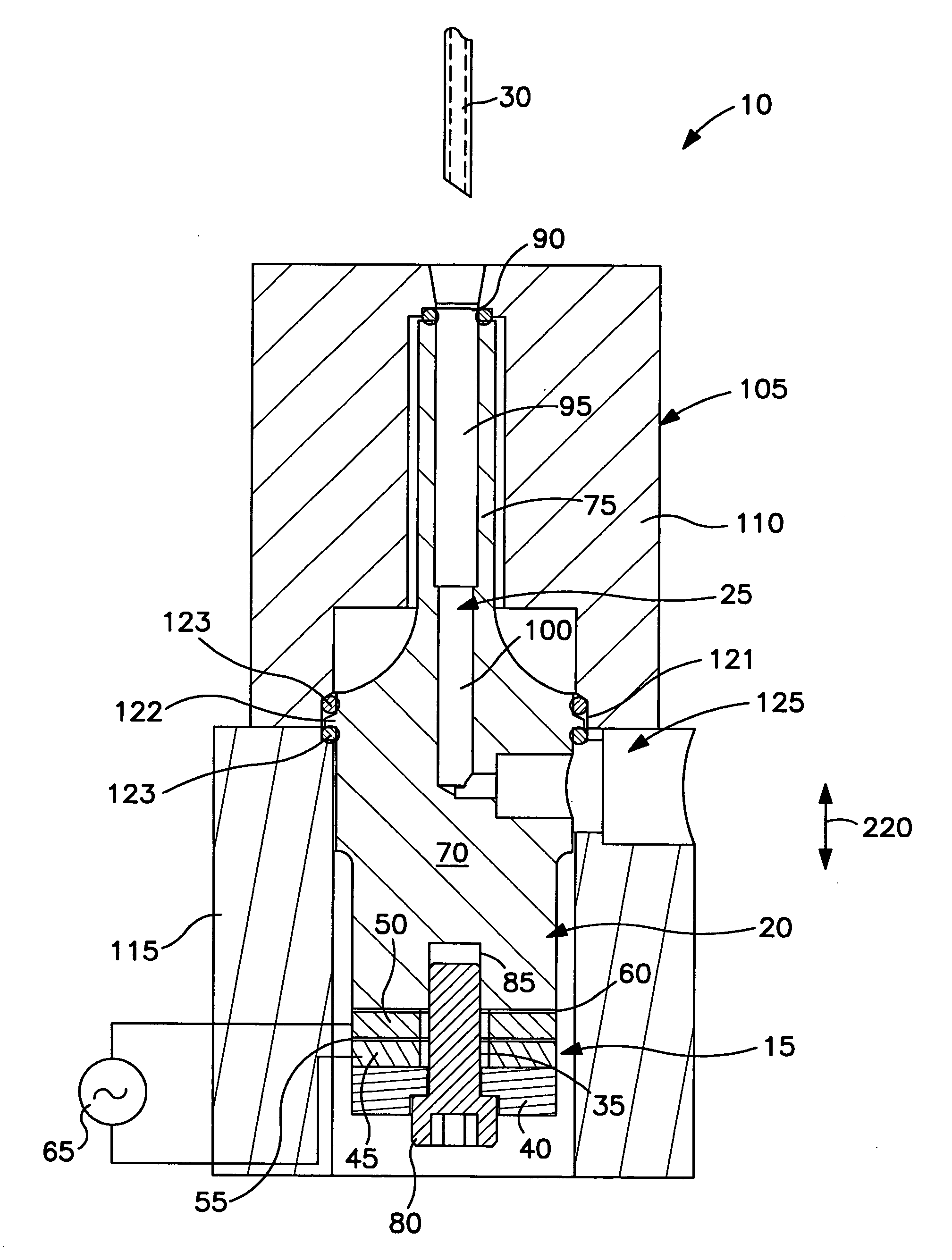
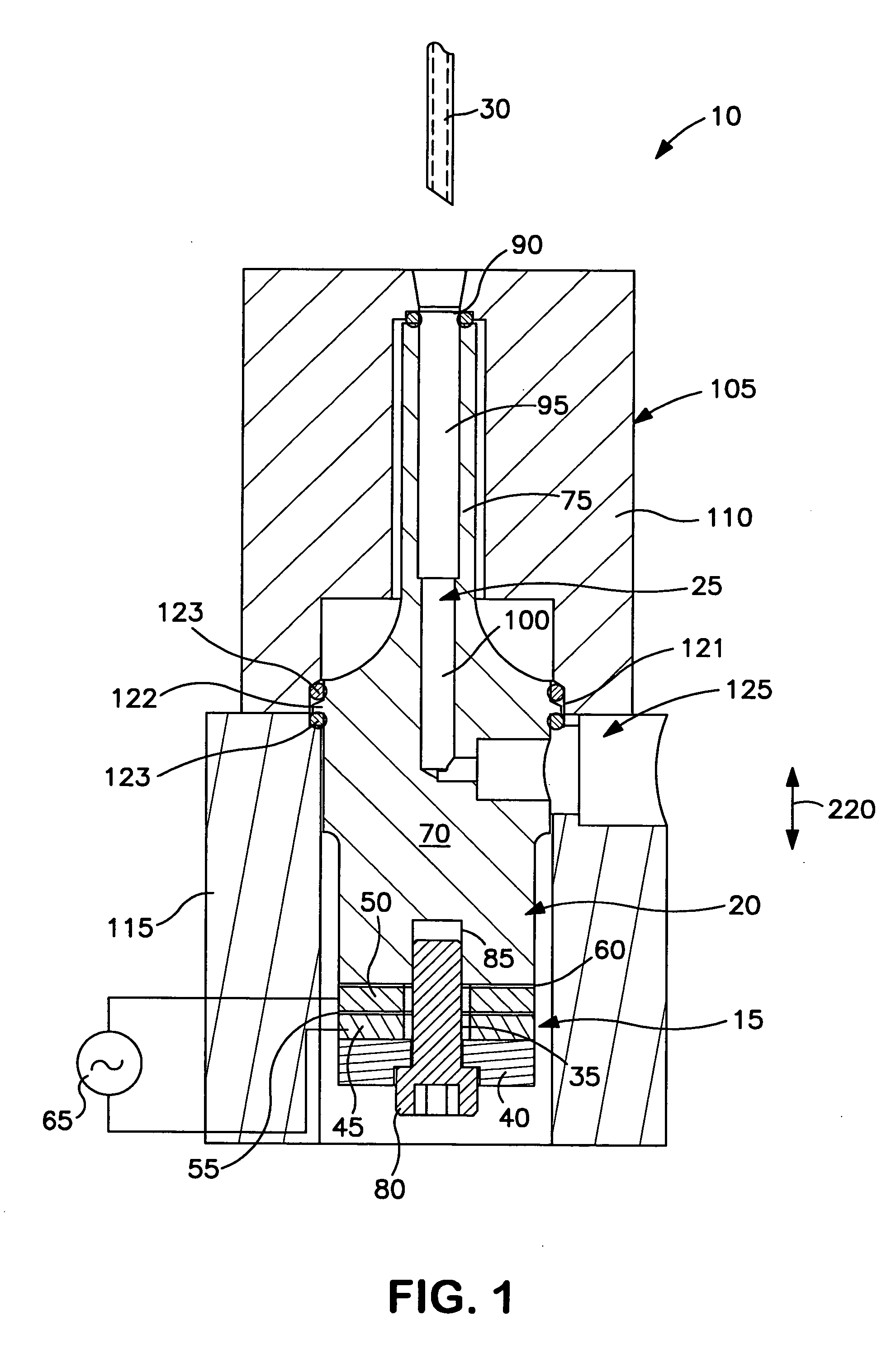
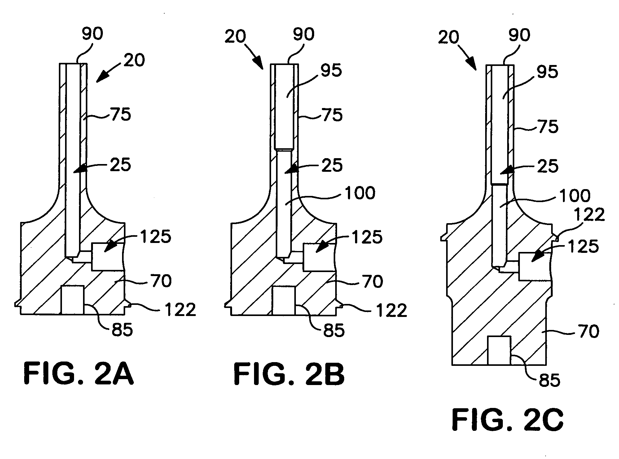
[0016] One embodiment of an apparatus suitable for cleaning a probe or the like using ultrasonic energy is shown at 10 of FIG. 1. Generally stated, the apparatus 10 includes an ultrasonic wave generator 15 and an ultrasonic wave concentrator 20 having a wash cavity 25 formed therein. Preferably, the ultrasonic wave generator 15 and ultrasonic wave concentrator 20 form a resonant, half-wave structure at the desired ultrasonic frequency of operation. Wash cavity 25 is dimensioned to closely conform to an exterior portion of a probe 30. For example, wash cavity 25 may have an interior diameter between 3.1 and 3.8 millimeters to accommodate a probe 30 having an exterior diameter between 1.6 and 1.9 millimeters. Clearances between the interior wall of the wash cavity 25 and the exterior of a typical probe 30 preferably range between 0.6 and 1.1 millimeters in basic embodiments, although other clearances may likewise be employed. Although probe 30 and wash cavity of the illustrated embodi...


PUM


Abstract

An apparatus and corresponding method for ultrasonically washing a probe or the like are disclosed. The apparatus comprises an ultrasonic wave generator and an ultrasonic wave concentrator. The ultrasonic wave concentrator includes a body portion having a wash cavity. The wash cavity is shaped to generally conform to an exterior portion of the probe. A first end of the ultrasonic wave concentrator is adapted to receive ultrasonic energy produced by the ultrasonic wave generator. The ultrasonic energy received at the first end of the concentrator is focused into the wash cavity where it is used to wash the probe (or other object). A second end of the ultrasonic wave concentrator includes an aperture that is open to the wash cavity and is adapted to receive the probe and allow it to enter the wash cavity.

Description

FIELD OF THE INVENTION [0001] The present invention is generally directed to methods and apparatus used to wash a probe or the like in a laboratory instrument. More particularly, the present invention includes methods and apparatus that employ ultrasonic energy to wash such a probe or the like. BACKGROUND OF THE INVENTION [0002] In order to execute a desired preparation and / or analysis operation, laboratory instruments must frequently transfer a substance from one locus to another. Such transfers often include transporting predetermined volumes of liquid samples or reagents between sample containers, reagent containers, reaction cuvettes, and other receptacles. The particular tools used in these transfers include pipetters, sampling probes, etc. Often, these tools have elongated bodies with small cross-sections. Depending on the function of the tool, the elongated body may be hollow. [0003] One problem associated with tools of this type is the carryover of residual traces of a previ...

Claims


Application Information

Patent Timeline
IPC IPC(8): G01H17/00
CPCB06B3/02
Inventor WILSON, BRIAN D.
Owner BECKMAN COULTER INC
Learn More