
Nature hipbone device

a hipbone and hip technology, applied in the field of nature hipbone devices, can solve the problems of inability to completely integrate sheet steel with the femur in order to protect the femur, inconvenient operation, patient pain,

Inactive Publication Date: 2006-08-10
CHIENG POONUNG
View PDF7 Cites 24 Cited by
  • Summary
  • Abstract
  • Description
  • Claims
  • Application Information

AI Technical Summary

Benefits of technology

[0009] Therefore, it is the primary objective of the present invention to provide a nature hipbone device which is installed onto an artificial femoral head, and its accessories are fixed to secure the hip joint so that the device will not shift or fall off as the joint moves.
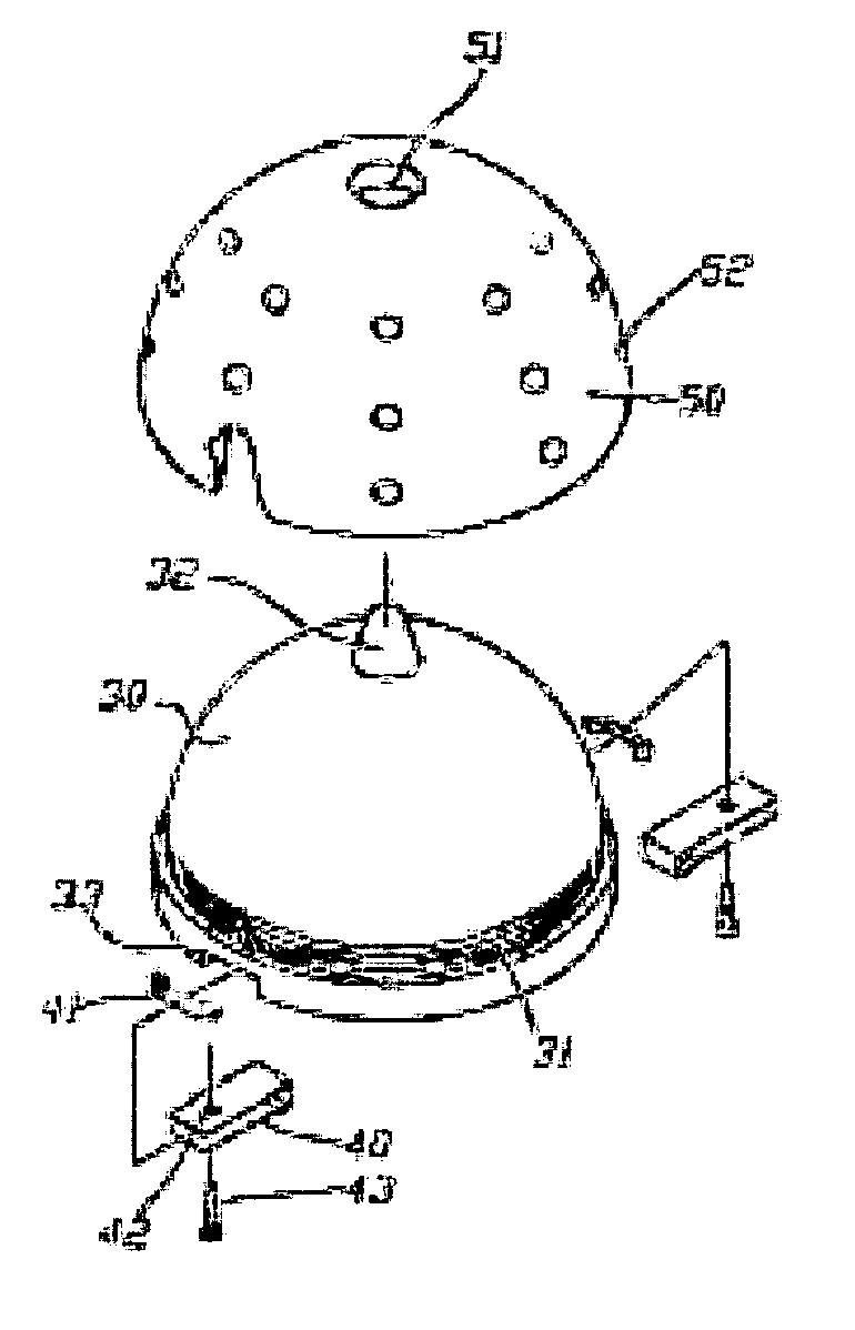
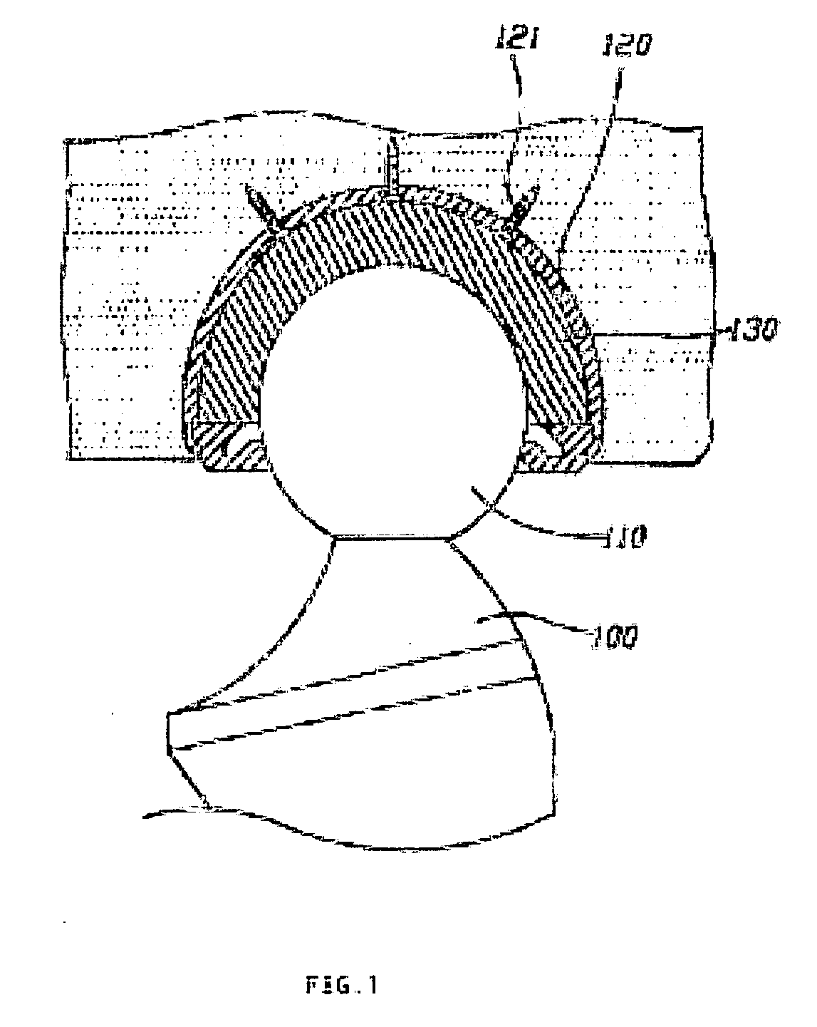
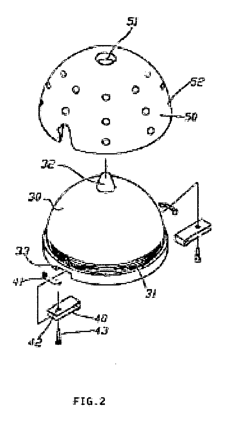
[0010] The nature hipbone device comprises a cotyle cup, and the internal wall of the cotyle cup is a very precise and smooth wall surface for directly receiving an artificial femoral head and minimizing the friction. The cotyle cup includes an orientation pivot and at least one pair of symmetrical link member disposed at the edge of an open end of the cotyle cup, a lock member disposed at a free end of each of the plurality of link member. When the nature hipbone device is in use, the femoral head is cut away and the femoral neck is kept, and then an artificial joint stem pivotally coupled to the artificial femur adjustable joint is inserted into the femur cavity and fixed at a predetermined position by the orientation pivots and locked into the hipbone by the lock member. As a result, the cotyle cup can be fixed into its position by means of the orientation pivots and the lock member at different positions and the cotyle cup can be integrally secured into the hip joint. The artificial femur adjustable joint is sheathed into the cotyle cup, so that the cotyle cup can move according to the movements of the hip joint, and the invention can prevent the cotyle cup from being slid or loosened.
[0011] Further, the cotyle cup includes a cup member corresponding to the shape of the cotyle cup, and the cup member includes a plurality of ribs around the cup member. When the cotyle cup is used, the femoral head is cut away and the femoral neck is kept, and then an artificial joint stem pivotally coupled to the artificial femur adjustable joint is inserted into the femur cavity and the cotyle cup is fixed at a predetermined position by the orientation pivots, and passed through the ribs embedded in the hipbone, so that the cotyle cup can be fixed into its position and secured to the hip joint. The artificial femur adjustable joint is sheathed into the cotyle cup, such that when the cotyle cup moves according to the movements of the femoral joint, the cotyle cup will not be slid or loosened by the pressing of the joint.
[0012] Further, when the cotyle cup is used, the femoral head is cut away and the femoral neck is kept, and then an artificial joint stem pivotally coupled to the artificial femur adjustable joint is inserted into the femur cavity and the cotyle cup is fixed at a predetermined position by the orientation pivots, and the through holes disposed on the cup member allow blood vessels and muscles to be penetrated deeply therein and integrated with the cotyle cup. Therefore, the cotyle cup can be fixed into its position. The artificial femur adjustable joint is sheathed into the cotyle cup, so that when the cotyle cup moves according to the movements of the femoral joint, the cotyle cup will not be slid or loosened by the pressing of the joint.

Problems solved by technology

However, the design of such a traditional structure has the following shortcomings: (1) The sheet steel cannot be secured; and (2) The newly grown blood vessels and bone crusts cannot cover the sheet steel effectively, so that the sheet steel cannot be integrated completely with the femur in order to protect the femur.
Further, the sheet steel cannot move according to the movements of the hip joint, which makes the application useless and the patient painful.
However, the application of this device has the following drawbacks:

Method used


Image

  • Nature hipbone device
  • Nature hipbone device
  • Nature hipbone device

Examples


Embodiment Construction

[0020] The above and other objects, features and advantages of the present invention will become apparent from the following detailed description taken with the accompanying drawing.

[0021] Referring to FIGS. 1 to 3 for the preferred embodiment of the present invention, a nature hipbone device of the invention comprises an artificial joint stem 100 being substantially in a curved shape corresponding to the shape of the femur. The artificial joint stem 100 is tapered from one end to the other end, and the end of the artificial joint stem 100 having a larger cross-sectional area is sheathed into a cotyle cup 30 made of a metal. The cotyle cup 30 adopts a nano technology or other method to make a very smooth surface of its walls, so that when the artificial femur adjustable joint 110 and the cotyle cup 30 are coupled with each other, almost no friction exists between the artificial femur adjustable joint 110 and the cotyle cup 30.

[0022] Further, the shape of the cotyle cup 30 correspo...


PUM


Abstract

The invention relates a nature hipbone device which includes a cotyle cup, an orientation pivot which localizes the cotyle cup in its place, is fixed on the close end of the cotyle cup; at least one link member which is hinged onto the opening edge of the end of the cotyle cup, at least one lock member which sleeve on the edge of an end of the link member apart from the cotyle cup may be located on secure place by the lock member.

Description

BACKGROUND OF THE INVENTION [0001] 1. Field of the Invention [0002] The present invention relates to a nature hipbone device, more particularly to a nature hipbone device installed onto an artificial femoral head, and its accessories are fixed to secure a hip joint so that the device will not shift or fall off as the hip joint is moving. [0003] 2. Description of the Related Art [0004] For the treatment of an injured femoral neck, the damaged part is generally cut away or sawn even and covered by a sheet steel, and then two nails are installed into the femur for fixing the sheet steel. However, the design of such a traditional structure has the following shortcomings: (1) The sheet steel cannot be secured; and (2) The newly grown blood vessels and bone crusts cannot cover the sheet steel effectively, so that the sheet steel cannot be integrated completely with the femur in order to protect the femur. The force exerted on the sheet steel at the damaged part is very limited, and thus t...

Claims


Application Information

Patent Timeline
IPC IPC(8): A61F2/34A61B17/56A61B17/68A61B17/86A61F2/00A61F2/30A61F2/32A61F2/36
CPCA61B17/68A61B17/86A61F2/32A61F2/34A61F2/36A61F2/367A61F2002/30169A61F2002/3038A61F2002/30406A61F2002/305A61F2002/30505A61F2002/30578A61F2002/30604A61F2002/30685A61F2002/30787A61F2002/3085A61F2002/30934A61F2002/3241A61F2002/3401A61F2002/3403A61F2002/3438A61F2002/3458A61F2002/3493A61F2002/3611A61F2220/0025A61F2220/0033A61F2230/0047A61F2310/00011A61F2002/30331A61F2002/30593A61F2002/3456
Inventor CHIENG, POONUNG
Owner CHIENG POONUNG
Learn More