
Peristaltic pump providing simplified loading and improved tubing kink resistance

a peristaltic pump and tubing technology, applied in the field of peristaltic pumps, can solve the problems of kink resistance of end clamps, large manipulation, and loading tubing, and achieve the effect of simplifying loading

Inactive Publication Date: 2006-08-10
VERATHON
View PDF25 Cites 26 Cited by
  • Summary
  • Abstract
  • Description
  • Claims
  • Application Information

AI Technical Summary

Benefits of technology

[0008] In view of the foregoing, it is an object of the present invention to provide a peristaltic pump having simplified loading.
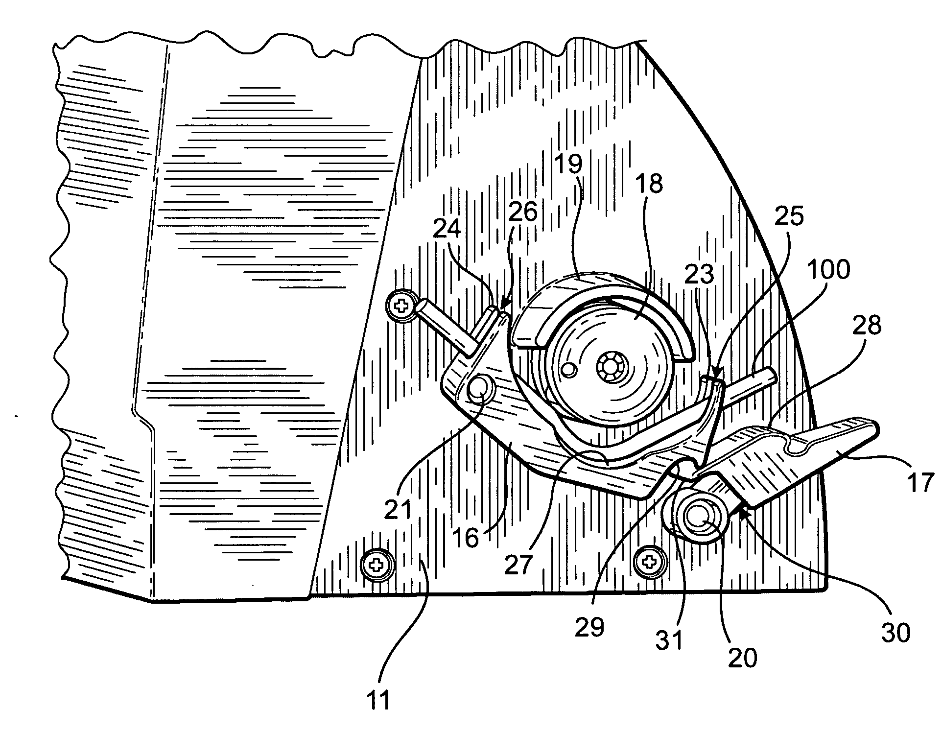
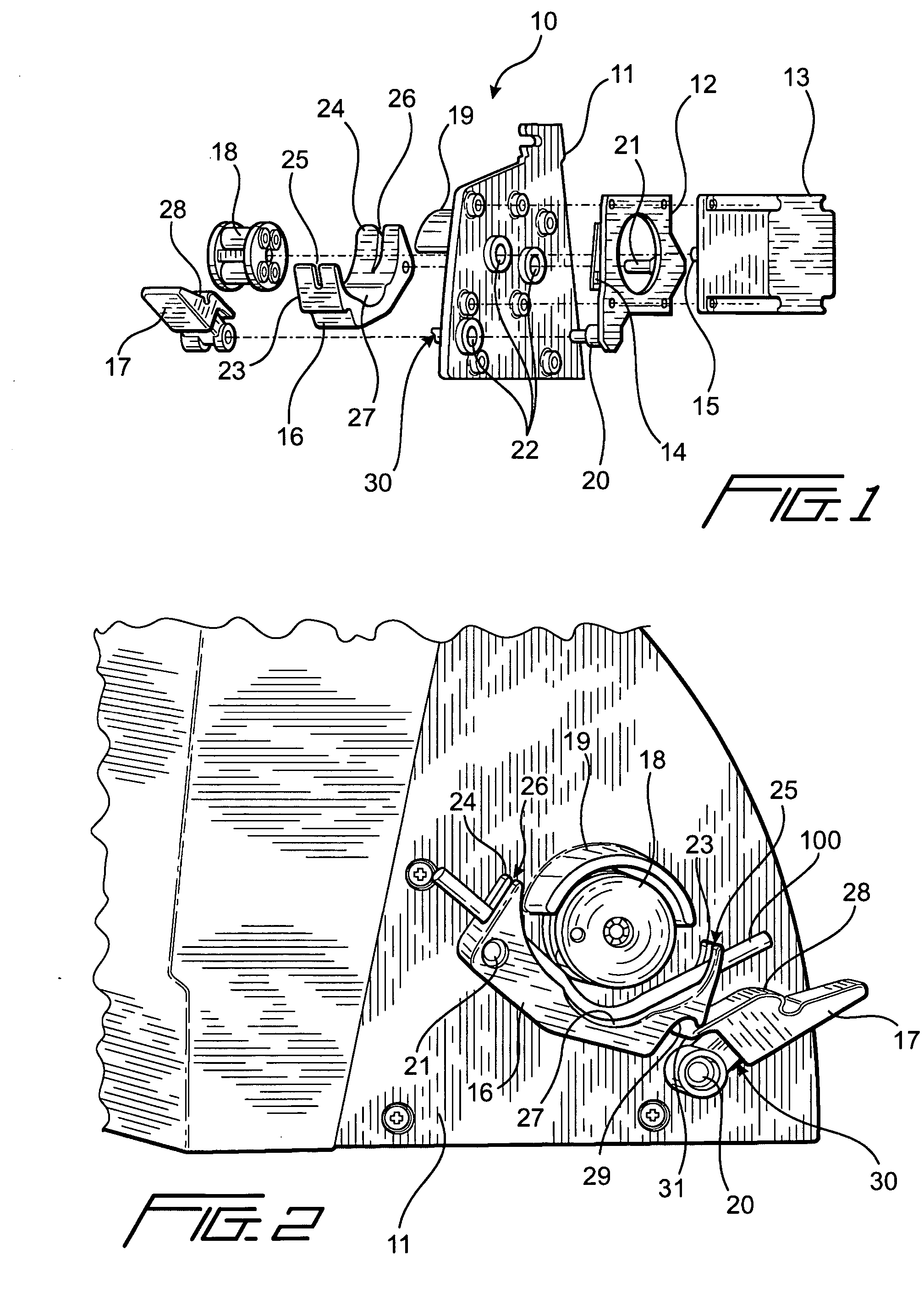
[0011] These and other objects of the present invention are accomplished by providing a peristaltic pump having a compression arm that self-centers the tubing during loading, without the use of additional clamps located on the pump housing. The compression arm is biased against the pump wheel with a single, easy to manipulate clamp that incorporates a spring biasing mechanism. The simplified construction of the peristaltic pump of the present invention thereby reduces loading time with respect to clamp manipulation, provides self-centering of the tubing and enhanced resistance to kinking.
[0013] The compression arm is arranged to pivot relative to the pump wheel to permit easy loading of the tubing, and includes a notch that mates with a projection of the clamp when the compression arm is locked into an engaged position with the pump wheel. To load the tube, the clamp is disengaged and the compression arm is rotated away from the pump wheel. The tubing then is inserted into the slots of the pinch forks, and the compression arm rotated against the pump wheel. The clamp is then engaged, thereby locking the compression arm and tubing against the rollers of the pump wheel.

Problems solved by technology

One drawback associated with conventional peristaltic pumps involves difficulty in loading tubing, in that it may require considerable manipulation to arrange the tubing in the end clamps to ensure that the tubing is properly centered in the pump mechanism.
Another drawback associated with conventional peristaltic pumps is that the tubing, when inadvertently placed in tension, has a tendency to kink against the end clamps during operation.
A still further drawback is associated with maintaining the tubing centered on the pump wheel rollers.

Method used


Image

  • Peristaltic pump providing simplified loading and improved tubing kink resistance
  • Peristaltic pump providing simplified loading and improved tubing kink resistance
  • Peristaltic pump providing simplified loading and improved tubing kink resistance

Examples


Embodiment Construction

[0021] Referring to FIG. 1, peristaltic pump 10 of the present invention includes pump wall 11 that defines interior and exterior surfaces of the pump. Mounting plate 12, which supports motor 13 and sensor 14, are mounted to the interior surface of the pump wall 11 so that shaft 15 of motor 13 extends through the pump wall to the exterior surface. Compression arm 16, clamp 17 and pump wheel 18 are mounted to the exterior of pump wall 11. The exterior of pump wall 11 further includes guard 19 that protects incidental contact with the exterior of pump wheel 18.

[0022] Motor 13 may be an electric motor and is the drive mechanism for pump 10. In a preferred embodiment, motor 13 may be microprocessor controlled using system software comprising machine-readable or interpretable instructions for controlling the rotation of pump wheel. More preferably, motor 13 may be activated in accordance with signals generated by sensor 14 that indicate the status of compression arm 16.

[0023] Mounting ...


PUM


Abstract

A peristaltic pump is provided that simplifies the loading of tubing and automatically self-centers the tubing relative to the pump wheel, wherein the pump includes an elongated arm having slotted pinch forks for engaging the tubing. The pinch forks are arranged substantially tangential to the pump wheel to reduce tubing kinking. The pump further includes a spring-loaded clamp that moves the elongated arm between engaged and disengaged positions, the clamp optionally including a sensor element used to detect when the pump is ready for operation.

Description

FIELD OF THE INVENTION [0001] The present invention relates to a peristaltic pump that provides simplified loading and improved kink-resistance. BACKGROUND OF THE INVENTION [0002] Peristaltic pumps are widely used in the medical industry for pumping fluids and are preferred for their positive displacement and flow metering characteristics. In addition, because the fluid to be pumped is contained within replaceable tubing, the pump mechanism does not become contaminated with the fluid. Typically, in such pumps a flexible tube is engaged with one or more rollers that periodically compress the tubing in a lengthwise fashion, thereby propelling the fluid disposed within the tubing. [0003] In a typical peristaltic pump, the flexible tubing is disposed between a spring-biased semi-circular clamp and the periphery of a pump wheel, with further end clamps disposed on the pump housing at either end of the semi-circular clamp to retain the tubing centered on the pump wheel. The pump wheel car...

Claims


Application Information

Patent Timeline
IPC IPC(8): F04B43/12
CPCF04B43/1253
Inventor NORDELL, BENJAMIN T.EDELSTEIN, PETER S.THOMAS, SIMON W.H.
Owner VERATHON
Learn More