Eureka AIR delivers breakthrough ideas for toughest innovation challenges, trusted by R&D personnel around the world.

Turnaround device

a turning device and walker technology, applied in the field of modified walker, can solve the problems of difficult if not impossible repositioning, difficult for a person using a walker to turn around to face the opposite direction, and the walker known in the art is difficult to maneuver,

Inactive Publication Date: 2006-07-27
GRANA CLARE +1
View PDF18 Cites 15 Cited by
  • Summary
  • Abstract
  • Description
  • Claims
  • Application Information

AI Technical Summary

Benefits of technology

[0006] One aspect of the present invention is directed to a turnaround device that includes a walker frame and a rotating structure for turning the walker frame from a first position to a second position without a person having to lift the walker frame between the first position and the second position. In one embodiment, the walker frame has a left side member and a right side member that each include downwardly extending front and rear legs. The side members may be held rigidly spaced apart by at least one front frame member.
[0013] Certain aspects of the present invention are directed to a turnaround device comprising, a walker frame having at least one downwardly extending leg; and a rotating structure for turning the walker frame from a first position to a second position, without a person having to lift the walker frame between the first position and the second position. In certain embodiments, the walker frame may have three downwardly extending legs.

Problems solved by technology

Walkers known in the art can be difficult to maneuver, particularly when a user wishes to turn in place.
For example, when a person of limited mobility pulls himself up from a bed to a standing position using a walker, and then wishes to turn to sit in a chair, such as a wheel chair, repositioning can be difficult if not impossible depending on the strength and agility of the person.
Likewise, it can be difficult for a person using a walker to turnaround to face the opposite direction.

Method used


Image

  • Turnaround device
  • Turnaround device
  • Turnaround device

Examples


Embodiment Construction

[0024] Other objects and advantages of this invention will become evident from a study of the following description and accompanying drawings.

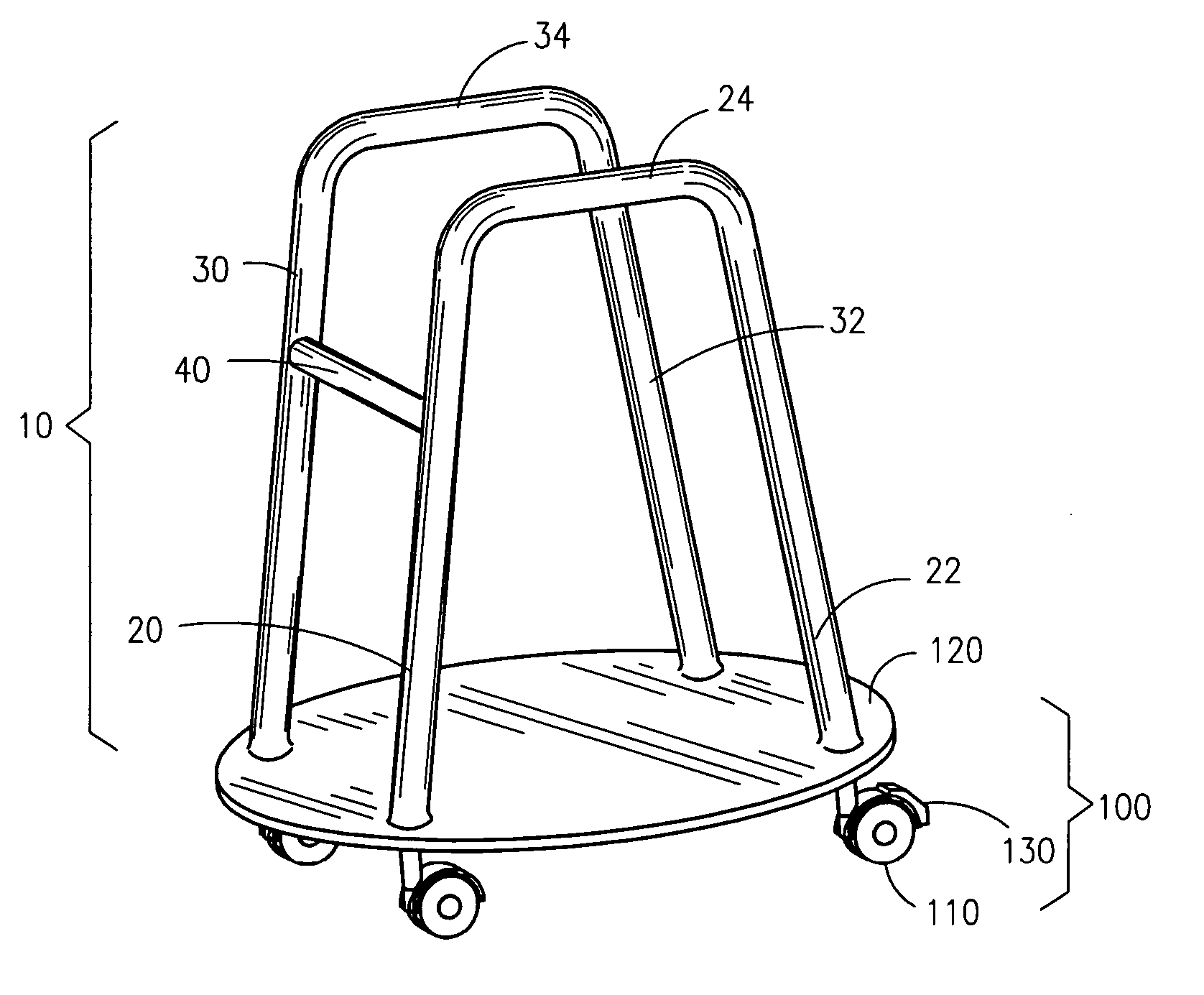
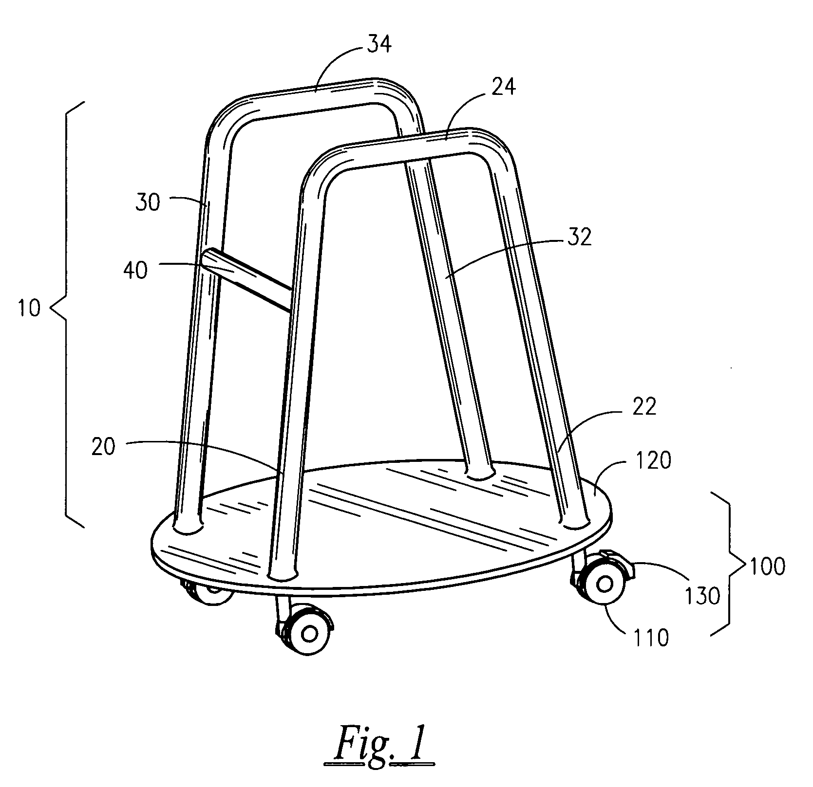
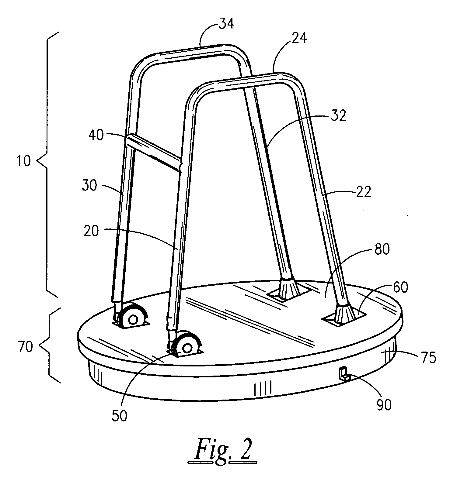
[0025]FIG. 1 depicts one embodiment of the present invention. The figure depicts a turnaround device having a walker frame 10. FIG. 1 illustrates walker frame 10 with a left side member 20, 22, 24 and a right side member 30, 32, 34. The left and right side members each include a downwardly extending front leg 20, 30 and a downwardly extending rear leg 22, 32. The front and rear legs of each side member are connected through a frame member 24, 34. It is understood that every described aspect of the invention may be modified to include either a right or left side member and that the legs may be vertical, essentially vertical, or set at various angles. In the walker frame, the side members may be held rigidly spaced apart by at least one front frame member 40. A person is meant to step into the walker frame 10 from the back between the rear legs...


PUM


Abstract

Modified walkers for use by persons having physical disabilities are provided. The modified walkers permit a person using the walker to more easily turn from one position to another.

Description

FIELD OF THE INVENTION [0001] The present invention relates to a modified walker for use by persons having physical disabilities. More specifically, the inventive walker relates to a device that permits a person using a walker to more easily turn from one direction to another without having to lift the walker. DESCRIPTION OF RELATED ART [0002] Walkers are commercially available for those physically handicapped persons having muscle weakness and / or lack of full muscle control that seriously affect normal walking motions and bodily balance. Such walkers aid a person that may be frail or who may have difficulty walking freely to move from place to place. For each one or more steps the user takes, the walker is lifted from the floor and repositioned on the walking surface a short distance in the direction the user is moving and in advance of taking additional steps. One type of walker in use today has a generally rectangular, tubular frame. The walker has four legs and is open at the re...

Claims


Application Information

Patent Timeline
Patent Type & Authority Applications(United States)
IPC IPC(8): A61H3/00
CPCA61H3/04A61H2003/043A61H2003/046
Inventor GRANA, CLARESWEENEY, BRIAN
Owner GRANA CLARE
Why Eureka
Eureka Blog
Learn More