
System and methods of deriving differential fluid properties of downhole fluids

a technology of differential fluid properties and downhole fluids, applied in seismology for waterlogging, borehole/well accessories, instruments, etc., to achieve the effects of reducing or eliminating systematic errors in measured data, robust and accurate comparisons, and reducing errors in downhole data measuremen

Active Publication Date: 2006-07-13
SCHLUMBERGER TECH CORP
View PDF14 Cites 49 Cited by
  • Summary
  • Abstract
  • Description
  • Claims
  • Application Information

AI Technical Summary

Benefits of technology

[0012] Applicants recognized that reducing or eliminating systematic errors in measured data, by use of novel sampling and downhole analysis procedures of the present invention, would lead to robust and accurate comparisons of formation fluids based on predicted fluid properties with reduced errors in downhole data measurements.
[0013] Applicants also recognized that quantifying levels of contamination in formation fluids and determining uncertainties associated with the quantified levels of contamination for the fluids would be advantageous steps toward deriving answer products of interest in oilfield exploration and development.
[0015] Applicants further recognized that quantifying uncertainty in predicted fluid properties of formation fluids would provide an advantageous basis for real-time comparison of the fluids, and is less sensitive to systematic errors in the data.
[0022] In yet another embodiment of the invention, a method of reducing systematic errors in downhole data comprises acquiring downhole data sequentially for at least a first and a second fluid at substantially the same downhole conditions with a device in a borehole.

Problems solved by technology

Uncertainties in fluid properties are derived from uncertainty in measured data and uncertainty in predicted contamination.

Method used


Image

  • System and methods of deriving differential fluid properties of downhole fluids
  • System and methods of deriving differential fluid properties of downhole fluids
  • System and methods of deriving differential fluid properties of downhole fluids

Examples


example

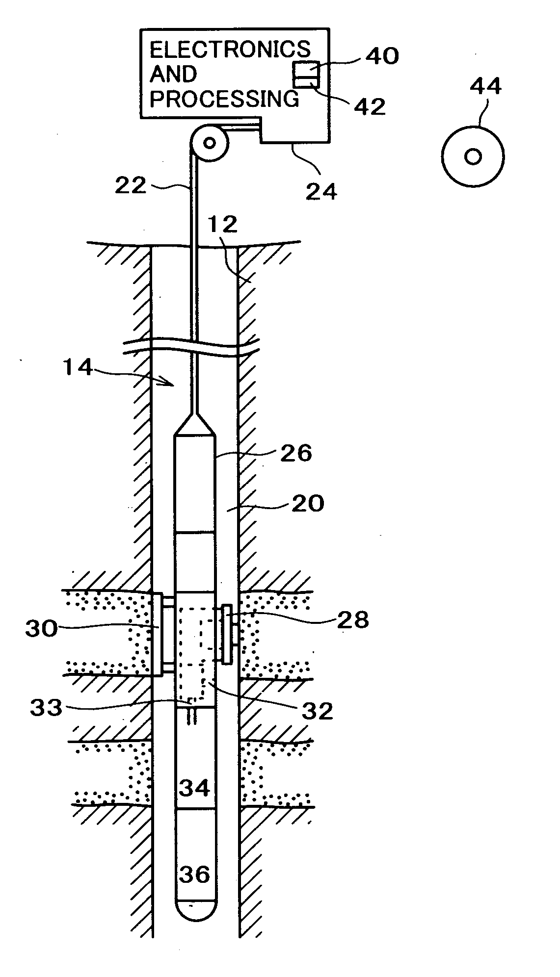
[0130]FIG. 15 shows a field data set obtained from a spectroscopy module (LFA) placed downstream of the pumpout module. The check-valves in the pumpout module were closed as the tool was moved from Station A to Station B, thus trapping and moving fluid A in the flowline from one station to the other. The initial part of the data until t=25500 seconds corresponds to fluid A at Station A. The second part of the data after time t=25500 seconds is from Station B.

[0131] At Station B, the leading edge of the data from time 25600-26100 seconds corresponds to fluid A and the rest of the data corresponds to fluid B. The different traces correspond to the data from different channels. The first two channels have a large OD and are saturated. The remaining channels provide information about color, composition, GOR and contamination of the fluids A and B.

[0132] Computations of difference in fluid properties and associated uncertainty include the following steps:

[0133] Step 1: The volumetric ...


PUM


Abstract

Methods and systems are provided for downhole analysis of formation fluids by deriving differential fluid properties and associated uncertainty in the predicted fluid properties based on downhole data less sensitive to systematic errors in measurements, and generating answer products of interest based on the differences in the fluid properties. Measured data are used to compute levels of contamination in downhole fluids using, for example, an oil-base mud contamination monitoring (OCM) algorithm. Fluid properties are predicted for the fluids and uncertainties in predicted fluid properties are derived. A statistical framework is provided for comparing the fluids to generate robust, real-time answer products relating to the formation fluids and reservoirs thereof. Systematic errors in measured data are reduced or eliminated by preferred sampling procedures.

Description

RELATED APPLICATION DATA [0001] The present application claims priority under 35 U.S.C. §119 to U.S. Provisional Application Ser. No. 60 / 642,781 (Attorney Docket No. 60.1601 US) naming L. Venkataramanan et al. as inventors, and filed Jan. 11, 2005; and under 35 U.S.C. §120 as a continuation-in-part of U.S. Non-Provisional application Ser. No. 11 / 132,545 (Attorney Docket No. 26.0290 US) naming L. Venkataramanan et al. as inventors, and filed May 19, 2005, now pending, the aforementioned applications being incorporated herein by reference in their entirety for all purposes.FIELD OF THE INVENTION [0002] The present invention relates to the analysis of formation fluids for evaluating and testing a geological formation for purposes of exploration and development of hydrocarbon-producing wells, such as oil or gas wells. More particularly, the present invention is directed to system and methods of deriving differential fluid properties of formation fluids from downhole measurements, such a...

Claims


Application Information

Patent Timeline
IPC IPC(8): G06F19/00
CPCE21B49/00E21B49/005
Inventor VENKATARAMANAN, LALITHAMULLINS, OLIVER C.VASQUES, RICARDO REVES
Owner SCHLUMBERGER TECH CORP
Learn More