
Grading control system

a control system and work machine technology, applied in the field of work machines, can solve the problems of impracticality for small jobs, long and tedious stake placement process, and increase the error of grade slope, and achieve the effect of raising and lowering the work implemen

Active Publication Date: 2006-06-15
CATERPILLAR INC
View PDF51 Cites 28 Cited by
  • Summary
  • Abstract
  • Description
  • Claims
  • Application Information

AI Technical Summary

Benefits of technology

[0008] In one exemplary aspect, a grading control system for a work machine having a work implement for grading along a grade defined by a laser plane generator is disclosed. The system includes a tilt actuator associated with the work implement and configured to tilt the work implement and a lift actuator associated with the work implement and configured to selectively raise and lower the work implement. A laser receiver is configured to receive a laser signal from the laser plane generator indicative of a desired grade. The laser receiver is configured to communicate a height signal based on the laser signal. The height signal may be indicative of a position of the work machine or work implement relative to the laser plane. A lift sensor is configured to communicate a lift signal indicative of a lift position of the work implement. A control module is in communication with the laser receiver and the lift sensor and is configured to generate a control signal based on the height signal and the lift signal. The control module is also configured to commun

Problems solved by technology

As the distance between stakes increases, the error in the grade slope may also increase.
Depending on the worksite, stake placement may be a lengthy and tedious process.
While these known systems are useful for some large excavations, they may be impractical for smaller jobs.
Motor graders and track-type bulldozer tractors may be unwieldy and / or uneconomical to operate at these worksites.
Therefore, the systems may be incapable of determining the position of the blade relative to the work machine.

Method used


Image

  • Grading control system
  • Grading control system
  • Grading control system

Examples


Embodiment Construction

[0013] Reference will now be made in detail to exemplary embodiments, examples of which are illustrated in the accompanying drawings. Wherever possible, the same reference numbers will be used throughout the drawings to refer to the same or like parts.

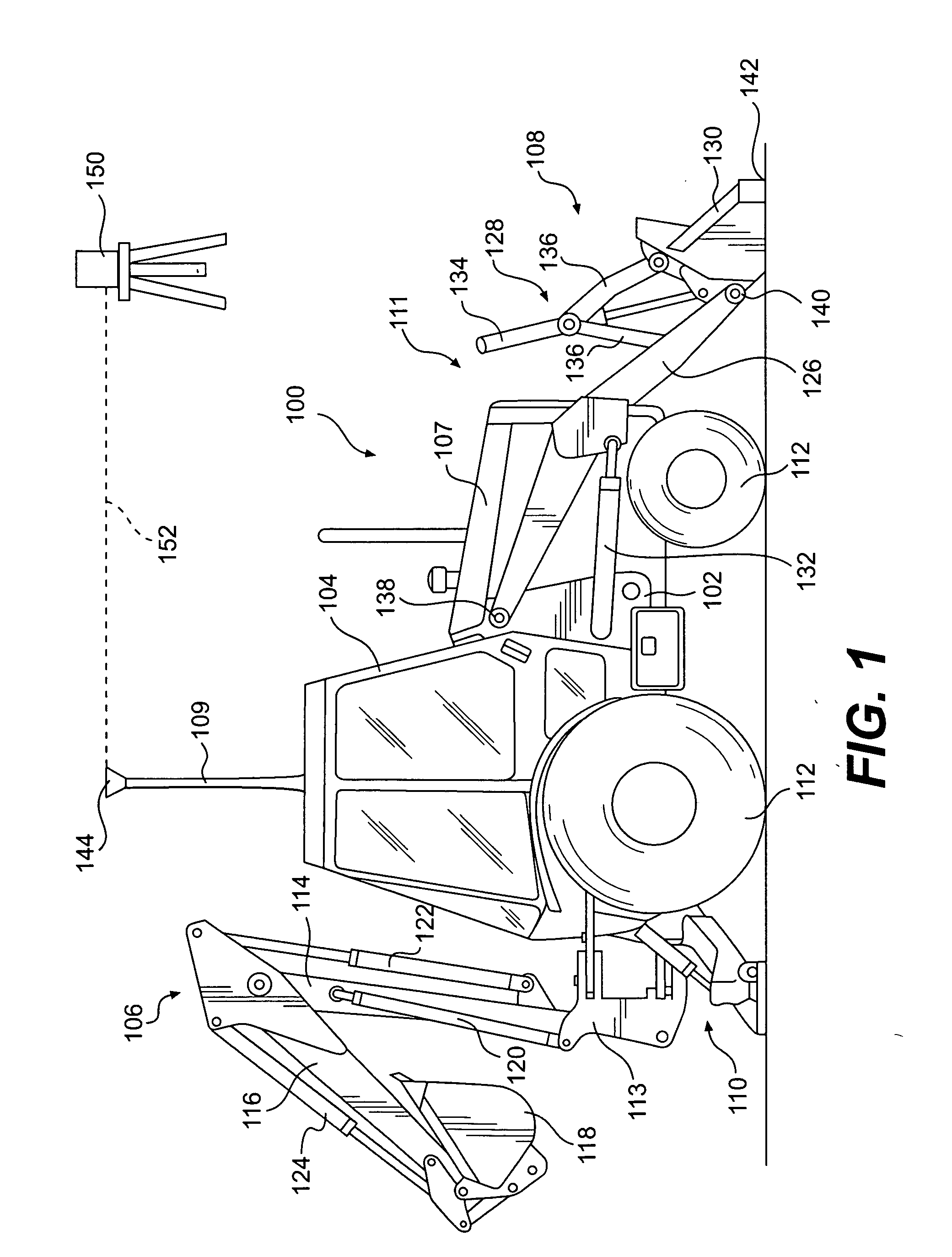
[0014] An exemplary embodiment of a backhoe loader 100 is illustrated in FIG. 1. Although this disclosure describes and references the backhoe loader 100, the systems and methods described herein could be equally applicable and useable by any loader type work machine including, for example, a wheel loader and a track loader. In the exemplary embodiment shown, the backhoe loader 100 includes a frame structure 102, an operator's station 104, a rear digging assembly 106, a front loader assembly 108, an engine compartment 107, and a laser mast 109. The rear digging assembly 106 and the front loader assembly 108 are supported by the frame structure 102 at a rear end 110 and a front end 111, respectively, of the backhoe loader 100.

[0015] T...


PUM


Abstract

A grading control system for a work machine having a work implement for grading along a grade defined by a laser plane generator is disclosed. The system includes tilt and lift actuators associated with the work implement and configured to selectively tilt, raise and lower the work implement. A laser receiver is configured to receive a laser signal indicative of a desired grade. The laser receiver is configured to communicate a height signal indicative of a position of the work machine relative to the laser plane. A lift sensor is configured to communicate a lift signal indicative of a lift position of the work implement. A control module is configured to generate and communicate a control signal based on the height and lift signals to actuate at least one of the lift and tilt actuators to maintain the work implement at a position substantially corresponding to the desired grade.

Description

TECHNICAL FIELD [0001] This disclosure is directed to a work machine, and more particularly, to a system and method for grading using a work machine. BACKGROUND [0002] Worksite preparations often include grading a worksite to form a specific, desired slope. Conventional grading may require that multiple grading stakes be placed about the worksite as reference points to ensure that the correct amount of material is removed or added to form the desired grade. The accuracy of the grade slope, however, may be dependent upon the number of grade stakes used and the distance between each grade stake. As the distance between stakes increases, the error in the grade slope may also increase. Accordingly, to minimize error in the grade slope, surveyors place stakes a limited distance apart. Depending on the worksite, stake placement may be a lengthy and tedious process. Further, during the actual grading, additional personnel often are needed to monitor the grade to ensure that the grade is wi...

Claims


Application Information

Patent Timeline
IPC IPC(8): E02F5/02B60D1/14B60D1/52B60R19/18B60R19/24E02F3/84
CPCE02F3/432E02F3/842E02F3/847E02F3/43
Inventor GLOVER, CLARENCE MATTHEW
Owner CATERPILLAR INC
Learn More