
Method and apparatus involving global positioning and long-range wireless link

Active Publication Date: 2006-05-25
SAVI TECH INC
View PDF17 Cites 79 Cited by
  • Summary
  • Abstract
  • Description
  • Claims
  • Application Information

AI Technical Summary

Problems solved by technology

The power levels of these wireless signals are limited by law.
However, in a military theater of operations, many of the items to be tracked may be on the enemy's side of a battle line, where it is impractical to install and / or maintain an array of multiple readers that can reliably read RFID tags.
Given the number of readers, the cost of installing these types of systems is relatively high.
However, a motion sensor cannot differentiate between movement of the item within a monitored area, and movement of the item out of the monitored area, for example due to theft.

Method used


Image

  • Method and apparatus involving global positioning and long-range wireless link
  • Method and apparatus involving global positioning and long-range wireless link
  • Method and apparatus involving global positioning and long-range wireless link

Examples


Embodiment Construction

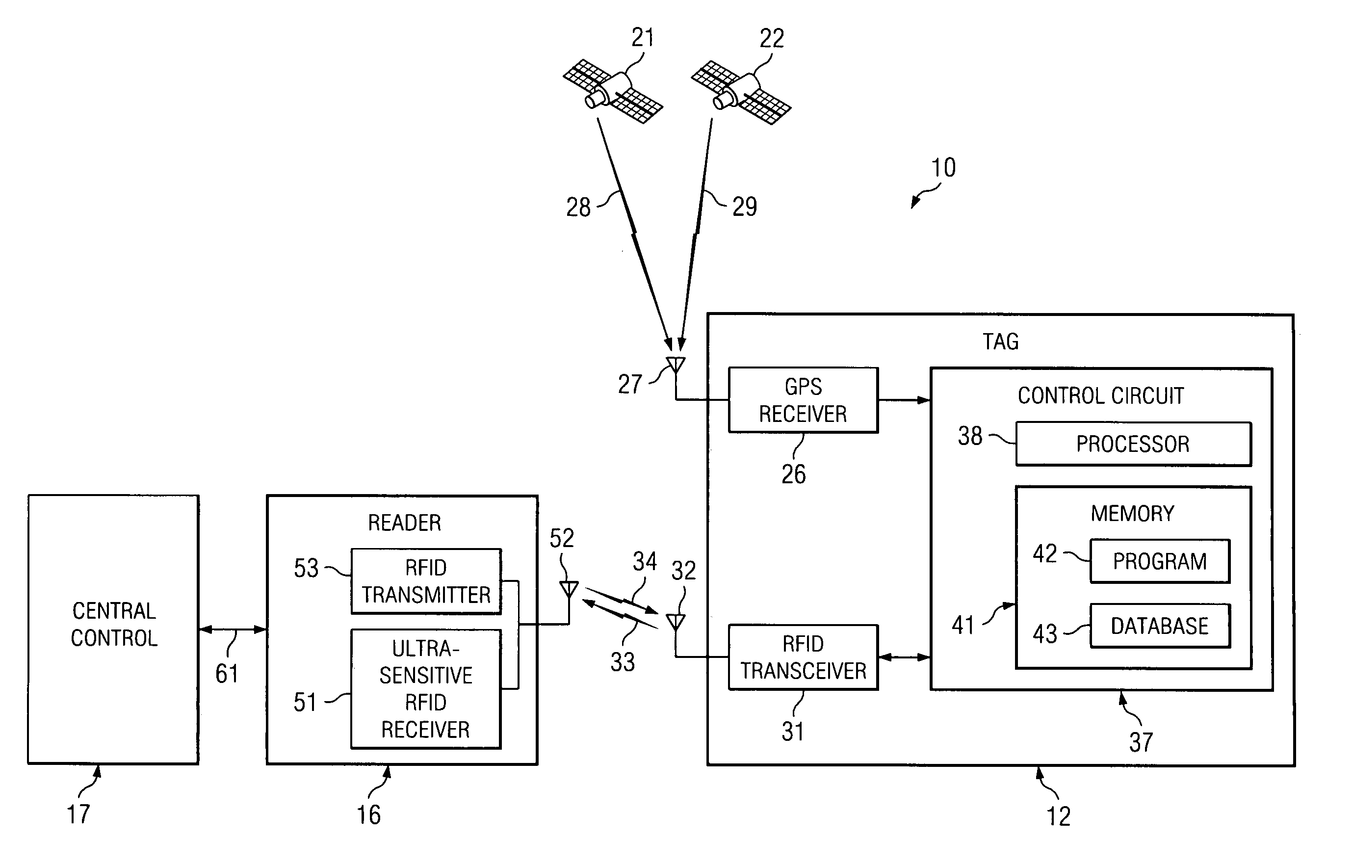
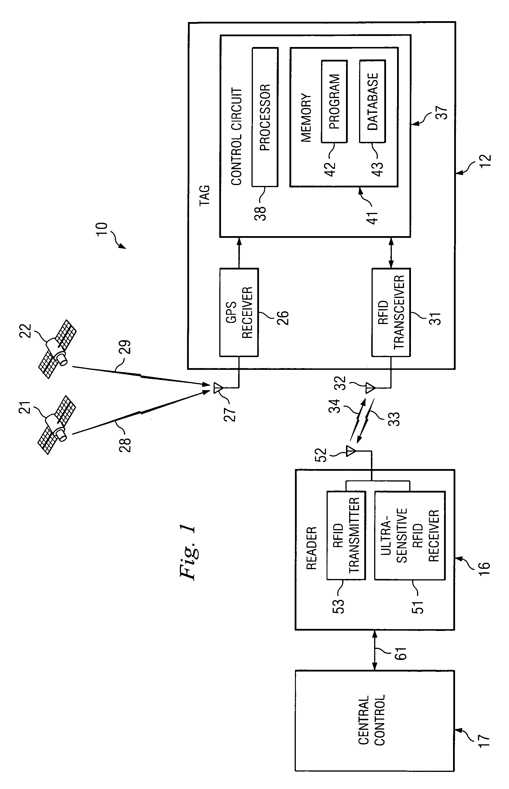
[0015]FIG. 1 is a block diagram of an apparatus 10 that embodies aspects of the present invention. The apparatus 10 includes a radio frequency identification (RFID) tag 12, a reader 16, a central control system 17, and a plurality of global positioning system (GPS) satellites, two of which are shown at 21 and 22. FIG. 1 does not show all of the components of the apparatus 10, but only those needed to convey an understanding of the invention.

[0016] The tag 12 includes a GPS receiver 26, and an antenna 27 through which the GPS receiver 26 can receive GPS radio signals 28 and 29 that are broadcast by the GPS satellites 21 and 22. The tag 12 also includes an RFID transceiver 31, and an antenna 32 through which the RFID transceiver 31 can transmit RFID radio signals at 33, and receive RFID radio signals at 34.

[0017] The tag 12 further includes a control circuit 37. The control circuit 37 has a processor 38 of a known type, and a memory 41. The memory 41 is shown diagrammatically, and m...


PUM


Abstract

A tag has a transmitter for transmitting first wireless signals, and a receiver for receiving second wireless signals from which the tag can determine its current physical location. A different embodiment includes a tag having a transmitter for transmitting wireless signals, and a reader having a receiver for receiving the wireless signals, the receiver in the reader being an ultra-sensitive receiver.

Description

[0001] This application claims the priority under 35 U.S.C. §119 of U.S. provisional application No. 60 / 629,479 filed Nov. 19, 2004, the disclosure of which is hereby incorporated herein by reference.FIELD OF THE INVENTION [0002] This invention relates in general to techniques for tracking items and, more particularly, to techniques for tracking items using radio frequency identification tags. BACKGROUND [0003] A known technique for tracking items is to mount a radio frequency identification (RFID) tag on each item to be tracked. These RFID tags transmit wireless signals, and readers are provided to receive these signals. The power levels of these wireless signals are limited by law. Consequently, in existing systems, the effective range of these wireless signals is typically only about 300 feet. [0004] One practical example of a tracking application is that items of military equipment are often tracked using RFID tags. However, in a military theater of operations, many of the items...

Claims


Application Information

Patent Timeline
IPC IPC(8): G08B1/08
CPCG01S5/0027G06Q10/08
Inventor RAJAPAKSE, RAVINDRA U.ZHU, LIPING JULIASHANNON, DAVID L.FARRELL, STEVEN J.
Owner SAVI TECH INC
Learn More