
Systems and methods for posterior dynamic stabilization of the spine

a dynamic stabilization and posterior technology, applied in the field of spinal disorders and pain, can solve the problems of affecting the ability of a spinal motion segment to properly function, eventual deterioration or disorder, and debilitating pain, and achieve the effect of facilitating fluoroscopic imaging

Active Publication Date: 2006-04-20
THE BOARD OF TRUSTEES OF THE LELAND STANFORD JUNIOR UNIV
View PDF99 Cites 623 Cited by
  • Summary
  • Abstract
  • Description
  • Claims
  • Application Information

AI Technical Summary

Benefits of technology

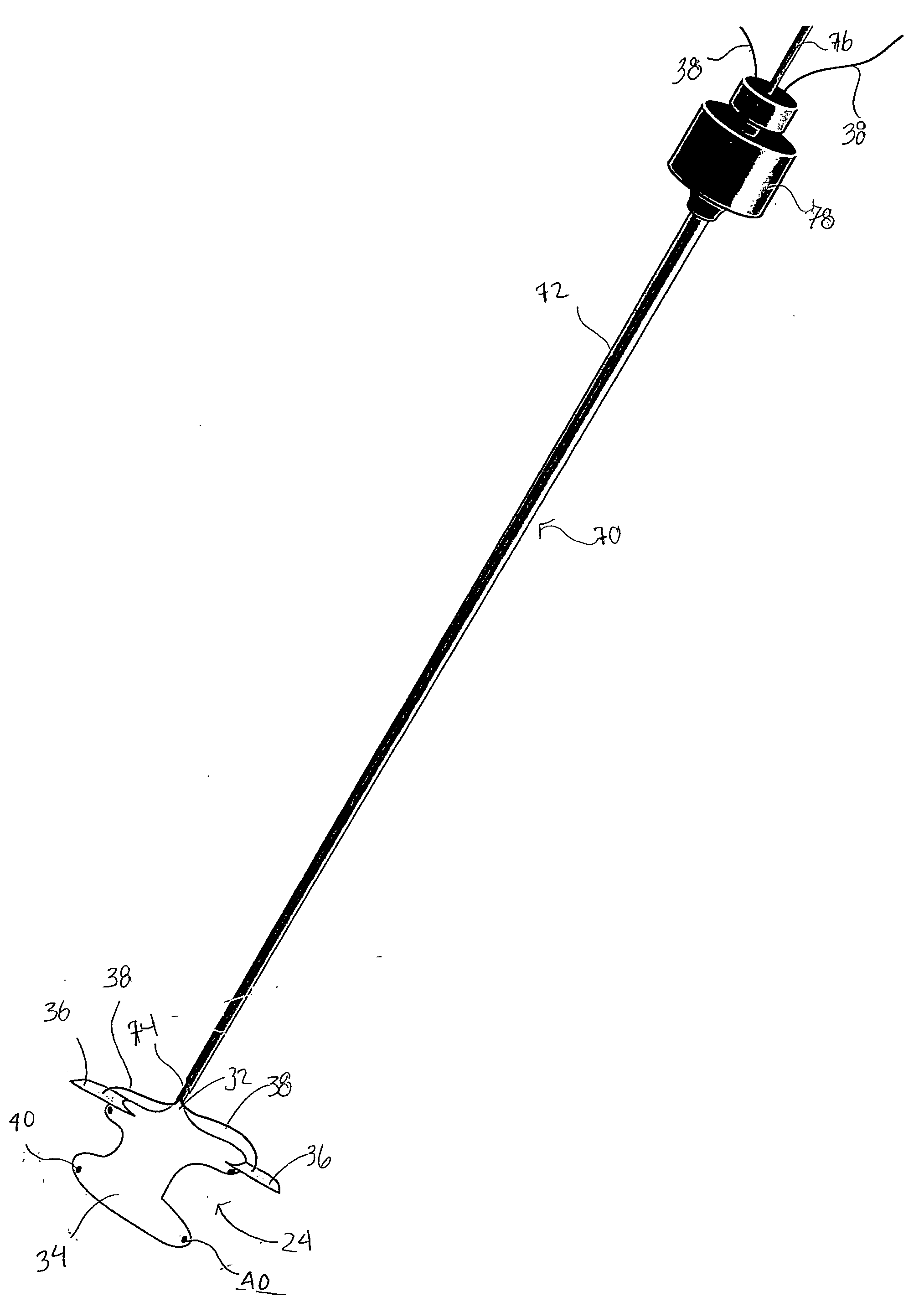
This patent describes devices that can help keep the spine stable by creating space between two neighboring bones (vertebral segments). These devices are designed to have an expandable part that can be filled with air or liquid to push the bones apart. They also have tabs to anchor them to the bones and sometimes markers to make it easier to see during X-ray images. Overall, this technology helps improve outcomes when treating degenerative disc disease or injuries affecting the spine.

Problems solved by technology

The technical problem addressed in this patent text is the development of better ways to treat spinal pain and related issues without resorting to fusion or static stabilization procedures. Both methods have advantages and disadvantages depending on individual cases, and research continues to improve them. There is a need for a dynamic stability system that addresses the issue of limited mobility and reduces stress on the spine.

Method used


Image

  • Systems and methods for posterior dynamic stabilization of the spine
  • Systems and methods for posterior dynamic stabilization of the spine
  • Systems and methods for posterior dynamic stabilization of the spine

Examples


Embodiment Construction

[0033] Before the subject devices, systems and methods are described, it is to be understood that this invention is not limited to particular embodiments described, as such may, of course, vary. It is also to be understood that the terminology used herein is for the purpose of describing particular embodiments only, and is not intended to be limiting, since the scope of the present invention will be limited only by the appended claims.

[0034] Unless defined otherwise, all technical and scientific terms used herein have the same meaning as commonly understood by one of ordinary skill in the art to which this invention belongs.

[0035] It must be noted that as used herein and in the appended claims, the singular forms “a”, “an”, and “the” include plural referents unless the context clearly dictates otherwise. Thus, for example, reference to “a spinal segment” may include a plurality of such spinal segments and reference to “the screw” includes reference to one or more screw and equival...


PUM


Abstract

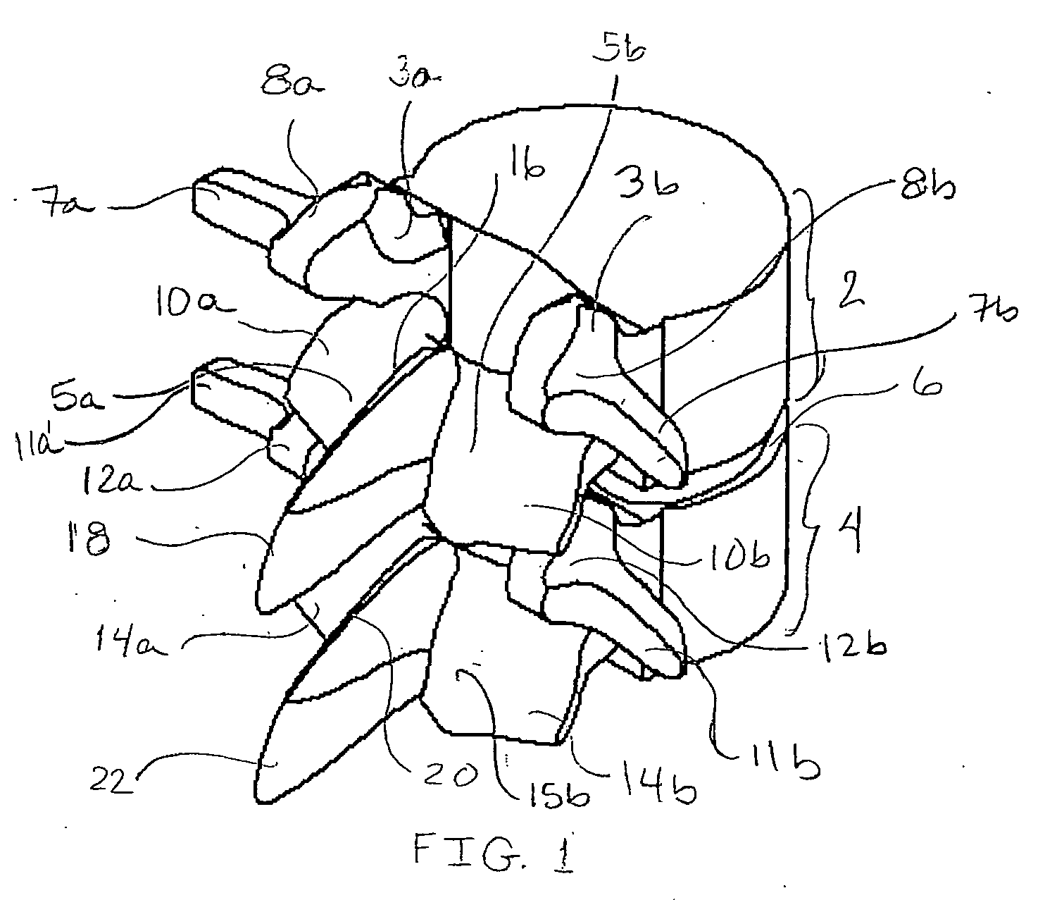
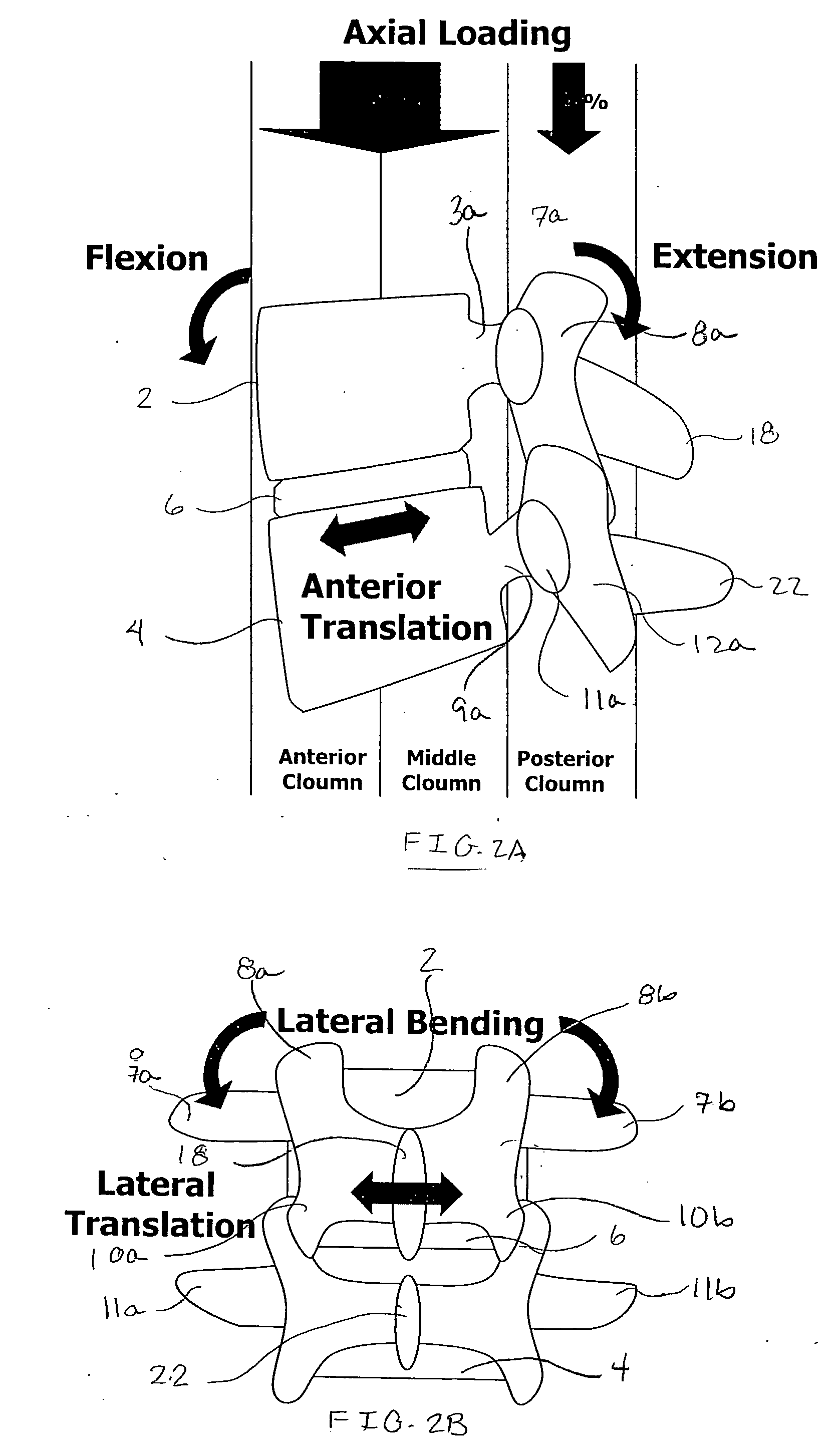
Devices, systems and methods for dynamically stabilizing the spine are provided. The devices include an expandable spacer or member having an unexpanded configuration and an expanded configuration, wherein the expandable member in an expanded configuration has a size, volume and/or shape configured for positioning between the spinous processes of adjacent vertebrae in order to distract the vertebrae relative to each other. The systems include one or more expandable members and an expansion medium for injection within or for filling the interior of the expandable member via the port. The methods involve the implantation of one or more devices or expandable spacers.

Description


Claims


Application Information

Patent Timeline
Owner THE BOARD OF TRUSTEES OF THE LELAND STANFORD JUNIOR UNIV
Learn More