
Buoyancy-based, underwater propulsion system and method

a propulsion system and underwater technology, applied in underwater equipment, special-purpose vessels, vessel construction, etc., can solve the problems of buoyant force acting on the diver and her equipment, sinking, and rising of the vessel, and achieve the effect of forward/backward and high drag

Active Publication Date: 2006-04-20
ADAMS PHILLIP M
View PDF18 Cites 7 Cited by
  • Summary
  • Abstract
  • Description
  • Claims
  • Application Information

AI Technical Summary

Benefits of technology

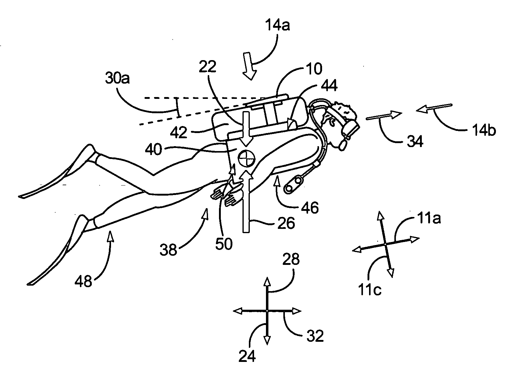
[0008] A diver may equip herself with the hydrofoil and buoyancy compensator before entering the water. Once underwater, the diver may use the buoyancy compensator to control the buoyant force acting on herself and her equipment. That is, by injecting air into the expander, the volume occupied by the expander may increase without increasing the overall mass of the diver, hydrofoil, and buoyancy compensator. In such a manner, the buoyant force acting on the diver and her equipment may increase, causing her to rise. Conversely, by dumping air from the expander, the volume occupied by the expander may decrease. Accordingly, the buoyant force acting on the diver and her equipment may decrease, causing her to sink.
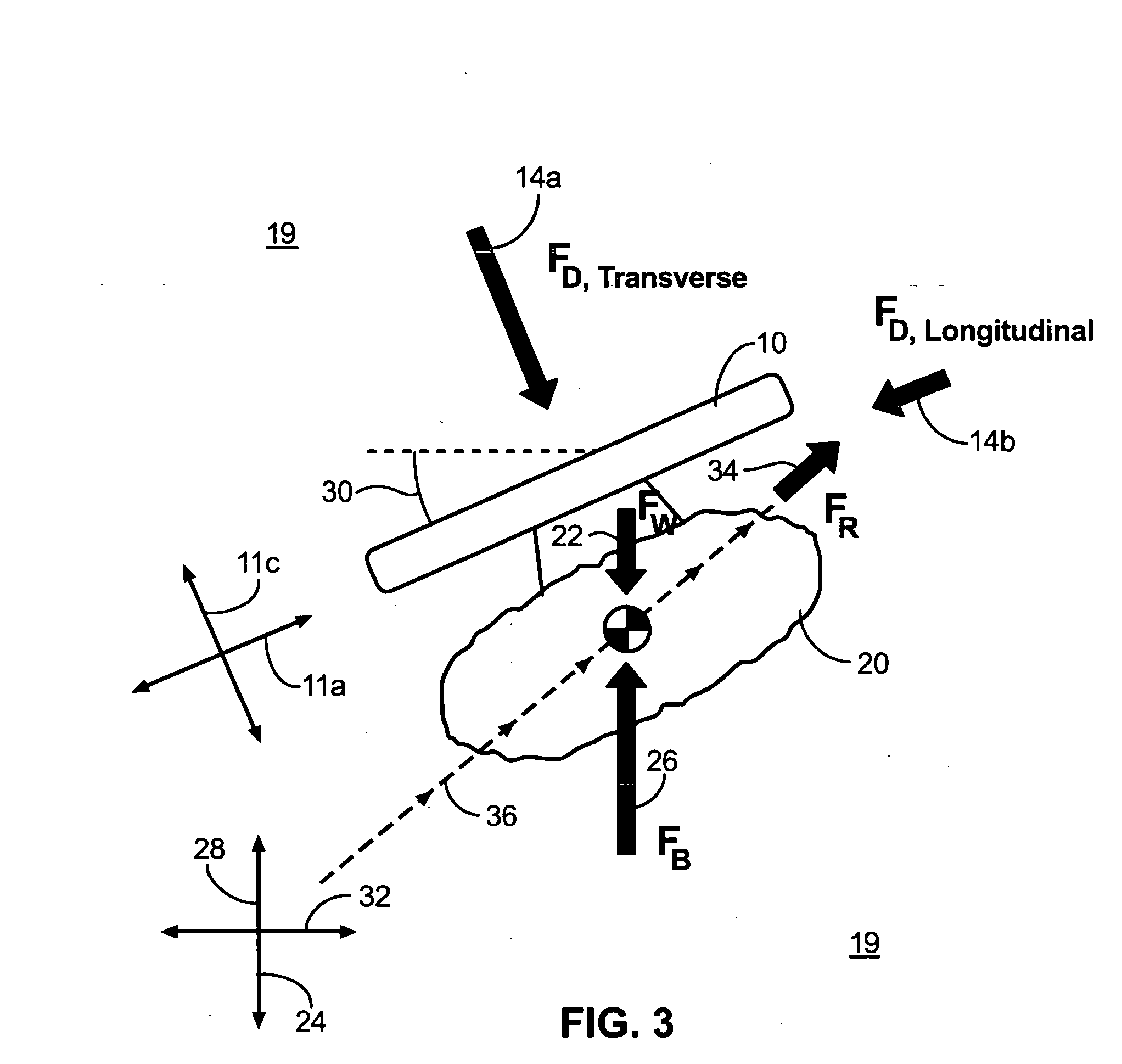
[0010] A diver may use a hydrofoil in accordance with the present invention to generate forward propulsion from the vertical rising or sinking caused by a buoyancy compensator. For example, when rising, a diver may orient the hydrofoil to a positive angle of attack. Differentials in the drag imposed on the hydrofoil by the water may urge the diver and hydrofoil forward. Similarly, when sinking, a diver may orient the hydrofoil to a negative angle of attack. Again, differentials in the drag (upward / downward=high drag; forward / backward=low drag) imposed on the projected relative shapes and sizes of the hydrofoil by the water may urge the diver and hydrofoil forward.

Problems solved by technology

In such a manner, the buoyant force acting on the diver and her equipment may increase, causing her to rise.
Accordingly, the buoyant force acting on the diver and her equipment may decrease, causing her to sink.

Method used


Image

  • Buoyancy-based, underwater propulsion system and method
  • Buoyancy-based, underwater propulsion system and method
  • Buoyancy-based, underwater propulsion system and method

Examples


Embodiment Construction

[0041] It will be readily understood that the components of the present invention, as generally described and illustrated in the Figures herein, could be arranged and designed in a wide variety of different configurations. Thus, the following more detailed description of the embodiments of the system and method of the present invention, as represented in the Figures, is not intended to limit the scope of the invention, as claimed, but is merely representative of selected embodiments of apparatus made in accordance with the invention. The invention will be best understood by reference to the drawings, wherein like parts are designated by like numerals throughout.

[0042] Referring to FIGS. 1 and 2, the shape and orientation of a body 10 placed within a flow 12, illustrated using streamlines 14, dramatically affect the drag 16 or resistance force 16 imposed on the body 10 by the flow 12. For example, a body 10 placed within a flow 12 generates a wake 18 or separation region 18. The siz...


PUM


Abstract

An apparatus for underwater propulsion. The apparatus may include a hydrofoil, a buoyancy compensator connected to the hydrofoil, a tank containing air, and a controller regulating the passage of air from the tank into the buoyancy compensator. The controller may also regulate the escape of air from the buoyancy compensator. By positioning the hydrofoil underwater and alternating between positive and negative angles of attack, a diver may generate forward propulsion by manipulating the controller to correspondingly alternate the buoyant force produced by the buoyancy compensator between levels below and above neutral buoyancy.

Description

BACKGROUND [0001] 1. The Field of the Invention [0002] This invention relates to underwater propulsion and, more particularly, to novel systems and methods for using buoyancy-based, vertical forces to generate forward motion. [0003] 2. The Background Art [0004] In the early 1940's, Jacques-Yves Cousteau and Emile Gagnan developed a regulator that automatically provided compressed air to a diver in response to inhalation. Prior to the Cousteau-Gagnan regulator, all self-contained underwater breathing devices supplied air continuously or required manual manipulation between on and off configurations. The Cousteau-Gagnan regulator begin a diving revolution that brought reliable and low cost diving to the masses. In 1993, just fifty years after the invention of the Cousteau-Gagnan regulator, the Professional Association of Diving Instructors (PADI) certified 515,000 new divers worldwide. [0005] In recent years, the popularity of other underwater diving activities such as snorkeling has ...

Claims


Application Information

Patent Timeline
Patent Type & Authority Applications(United States)
IPC IPC(8): B63C11/46
CPCB63C11/46
Inventor ADAMS, PHILLIP M.
Owner ADAMS PHILLIP M
Learn More