
Compact universal splint apparatus for focused immobilization such as of a single digit of the foot or hand, and method

a splint and universal technology, applied in the field of medical appliances, can solve the problems of obstructing swelling and circulation, difficult to adapt, and the size and shape of the splint is difficult to adap

Inactive Publication Date: 2006-03-30
MOSKOWITZ BARRY M
View PDF20 Cites 193 Cited by
  • Summary
  • Abstract
  • Description
  • Claims
  • Application Information

AI Technical Summary

Benefits of technology

"The present invention provides a splint apparatus that includes a rigid immobilization member and a flexible sheet with a retaining portion for the immobilization member and a body area engaging portion. The immobilization member can be adjusted in size and can be trimmed to fit different body parts. The flexible sheet has an arm portion with a fastening mechanism for securely positioning the splint apparatus around the body part. The technical effects of this invention include improved splinting flexibility, ease of adjustment, and secure positioning of the splint apparatus."

Problems solved by technology

Problems with these prior splints have been that they are not useful for more than one body area such as for both toes and fingers, they can be time consuming to apply, they are uncomfortable to the patient and difficult to adapt to the structure to be splinted, and they sometimes obstruct swelling and circulation.
Another problem has been that the size and shape of the splint is has been difficult to adapt to fit the particular digit or other body area of the individual patient, partly because of the materials used to construct prior splints.
Still another problem has been that some prior splints have been expensive to manufacture.
A problem with Ewing is that the splint does not permit the finger to enlarge in diameter with swelling.

Method used


Image

  • Compact universal splint apparatus for focused immobilization such as of a single digit of the foot or hand, and method
  • Compact universal splint apparatus for focused immobilization such as of a single digit of the foot or hand, and method
  • Compact universal splint apparatus for focused immobilization such as of a single digit of the foot or hand, and method

Examples


first preferred embodiment

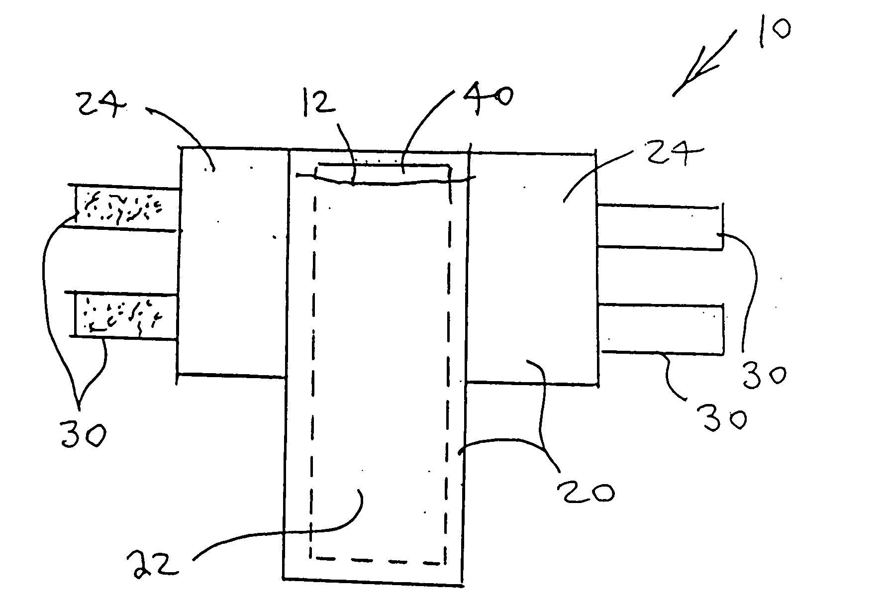
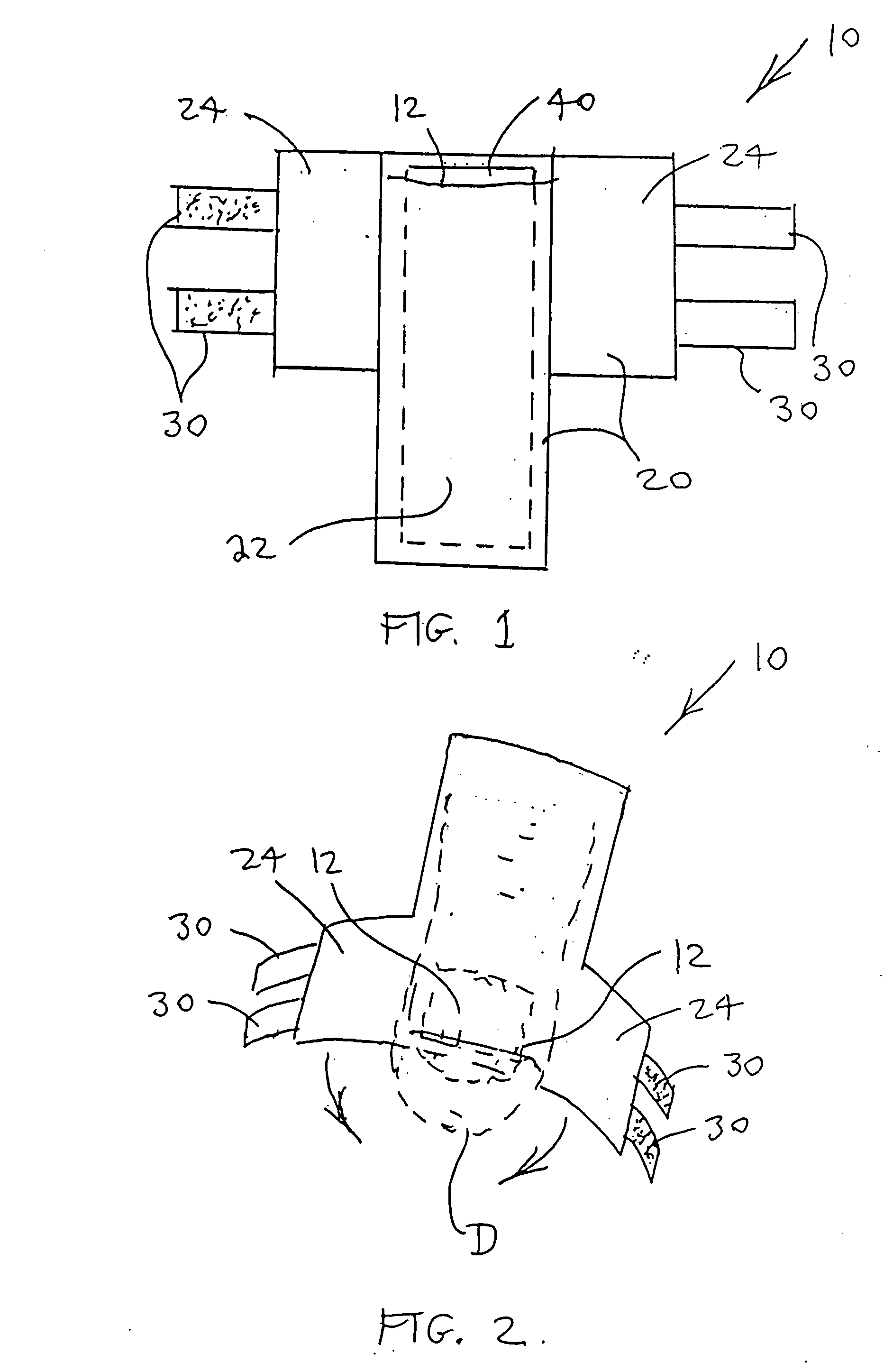
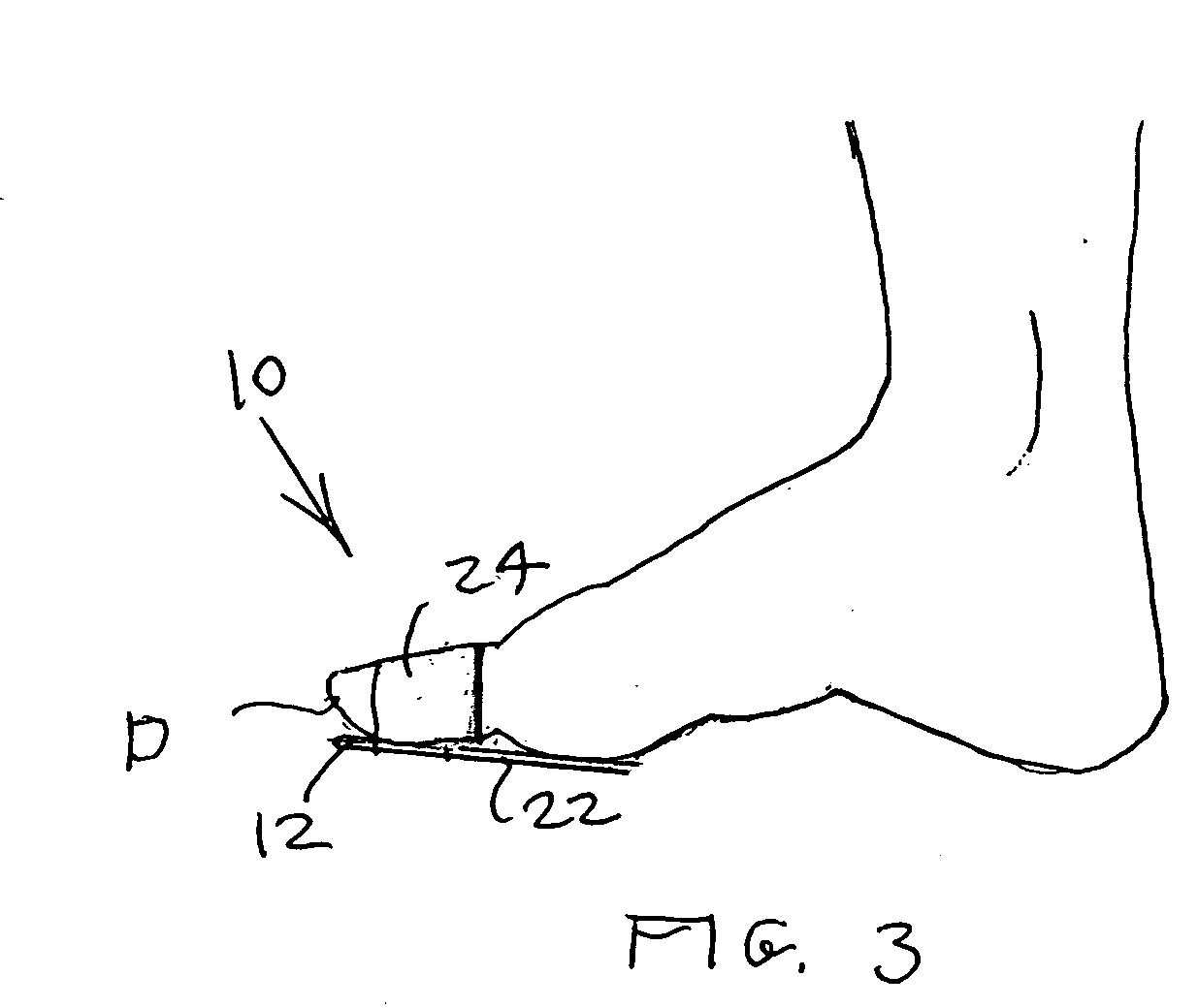
[0042] Referring to FIGS. 1-11, an open splint apparatus 10 is disclosed, including an apparatus mounting structure 20 and a substantially rigid (for purposes of the present specification and claims meaning either rigid or semi-rigid) immobilization member in the form of a thin immobilization panel 40 which can be removed from the apparatus mounting structure 20 for meeting virtually any immobilization need, such as for fracture. Apparatus mounting structure 20 preferably is substantially cross-shaped and for many applications is T-shaped, having a member retaining portion 22 and a body area engaging portion in the form of two arm portions 24 protruding from the member retaining portion 22 for wrapping around part of the human body, and preferably is formed of elastic sheet material to permit expansion and contraction with swelling size changes. Immobilization panel 40 is secured along the member retaining portion 22, and the member retaining portion 22 is placed along the length of...


PUM


Abstract

A splint apparatus includes an immobilization member which is substantially rigid; and an apparatus mounting structure including a flexible sheet and a immobilization member retaining structure removably retaining the immobilization member and body area engaging means. The immobilization member preferably is an immobilization panel. The body area engaging structure preferably includes at least one arm portion extending from the flexible sheet and having an arm portion free end for wrapping around a part of a human body, and having a arm portion fastening structure for removably securing the at least one arm portion remote end after the at least one arm portion is wrapped around a part of a human body. A method of using the splint apparatus to splint a part of a human body is also provided.

Description

BACKGROUND OF THE INVENTION [0001] 1. Field of the Invention [0002] The present invention relates generally to the field of medical appliances for placement on the human body. More specifically the present invention relates to an open universal splint apparatus having an apparatus mounting structure and a rigid immobilization member such as a thin immobilization panel sized in length and width and otherwise shaped to properly fit and individually immobilize virtually any foot or hand digit or adjoining body structure without immobilizing an adjacent digit, with easy splint apparatus application and removal. [0003] The apparatus mounting structure preferably is generally cross-shaped and for many applications is T-shaped, including a member retaining portion and a body area engaging portion in the form of two arm portions protruding from the member retaining portion for wrapping around a part of the human body, and preferably formed of elastic sheet material. The immobilization panel...

Claims


Application Information

Patent Timeline
Patent Type & Authority Applications(United States)
IPC IPC(8): A61F5/00
CPCA61F5/019A61F5/10A61F5/05875
Inventor MOSKOWITZ, BARRY M.
Owner MOSKOWITZ BARRY M
Learn More