
Measuring method of spatially resolved frequency selective images

a spatial resolution and selective image technology, applied in the field of spatial resolution spectroscopic recordings, can solve the problem of inefficient time-consuming measuring schemes, and achieve the effect of facilitating precise limitation of nmr measuremen

Inactive Publication Date: 2006-03-02
UNIV ZURICH +1
View PDF3 Cites 3 Cited by
  • Summary
  • Abstract
  • Description
  • Claims
  • Application Information

AI Technical Summary

Benefits of technology

The patented technology uses a special technique called magnetic gradients to create an electromagnetic environment that can be controlled during nuclear magnetic resonance (NMR) measurements. By adjusting these gradients, researchers have been able to precisely limit the area where signals are collected, which helps improve accuracy when analyzing samples. Additionally, by mapping the frequency spectrum into space, they were also able to generate detailed imaging data from the sample. Overall, this approach provides more accurate results and better understanding of materials being tested.

Problems solved by technology

The patent text describes a method for making spatially resolved spectroscopic recordings using nuclear magnetic resonance (NMR) techniques. The current method is time-efficient, but it may not be optimal for in-vivo applications due to power deposition. The technical problem addressed by the patent is to develop a more efficient method for making spatially resolved spectroscopic recordings that can be used in in-vivo applications without causing power deposition.

Method used


Image

  • Measuring method of spatially resolved frequency selective images
  • Measuring method of spatially resolved frequency selective images
  • Measuring method of spatially resolved frequency selective images

Examples


Embodiment Construction

[0048] The exemplifications set out herein are not to be construed as limiting the scope of this disclosure or the scope of this invention in any manner.

[0049] The nuclear magnetic resonance imaging system shown in FIG. 2 includes a set of main coils 10 whereby a steady, spatially uniform magnetic field is generated. The main coils are constructed, for example, in such a manner that they enclose a tunnel-shaped examination space. A patient to be examined is slid on a table into this tunnel-shaped examination space.

[0050] The magnetic resonance imaging system also includes a number of gradient coils 12, whereby magnetic fields exhibiting spatial variations, notably in the form of temporary gradients in individual directions, are generated so as to be superposed on the uniform magnetic field. The gradient coils 12 are connected to a controllable power supply unit 21. The gradient coils 12 are energized by application of an electric current by means of the power supply unit 21. The s...


PUM


Abstract

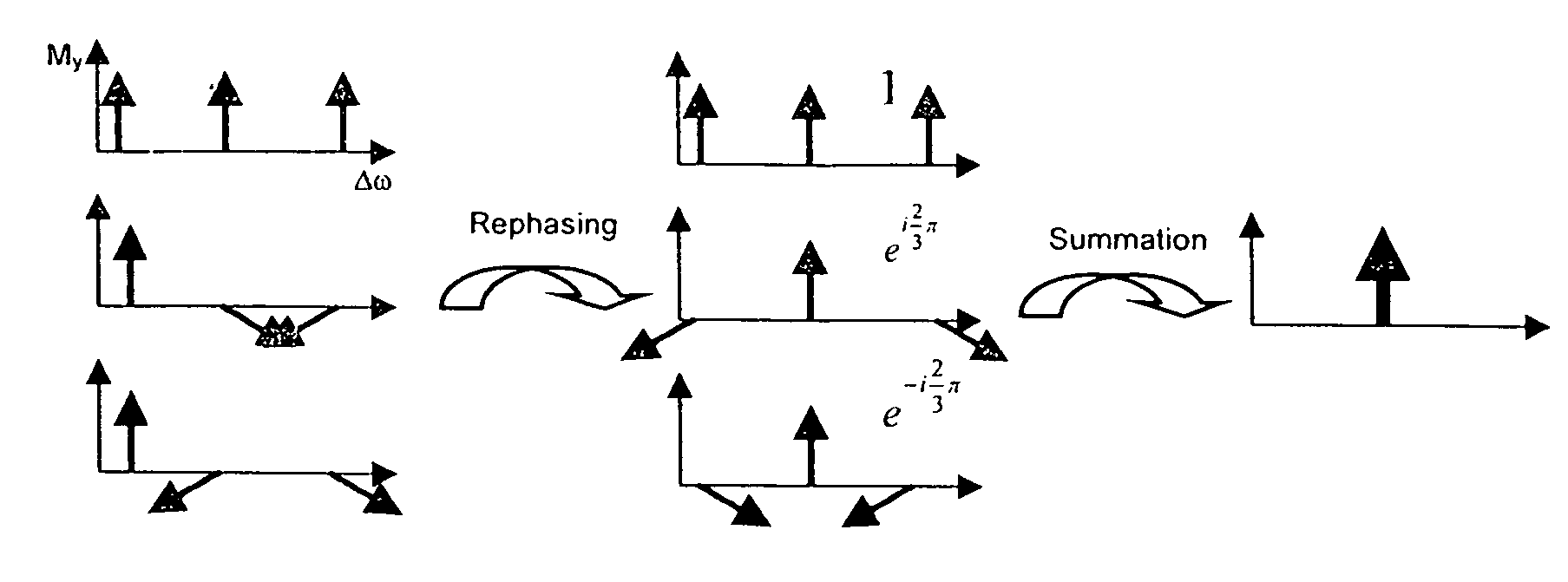
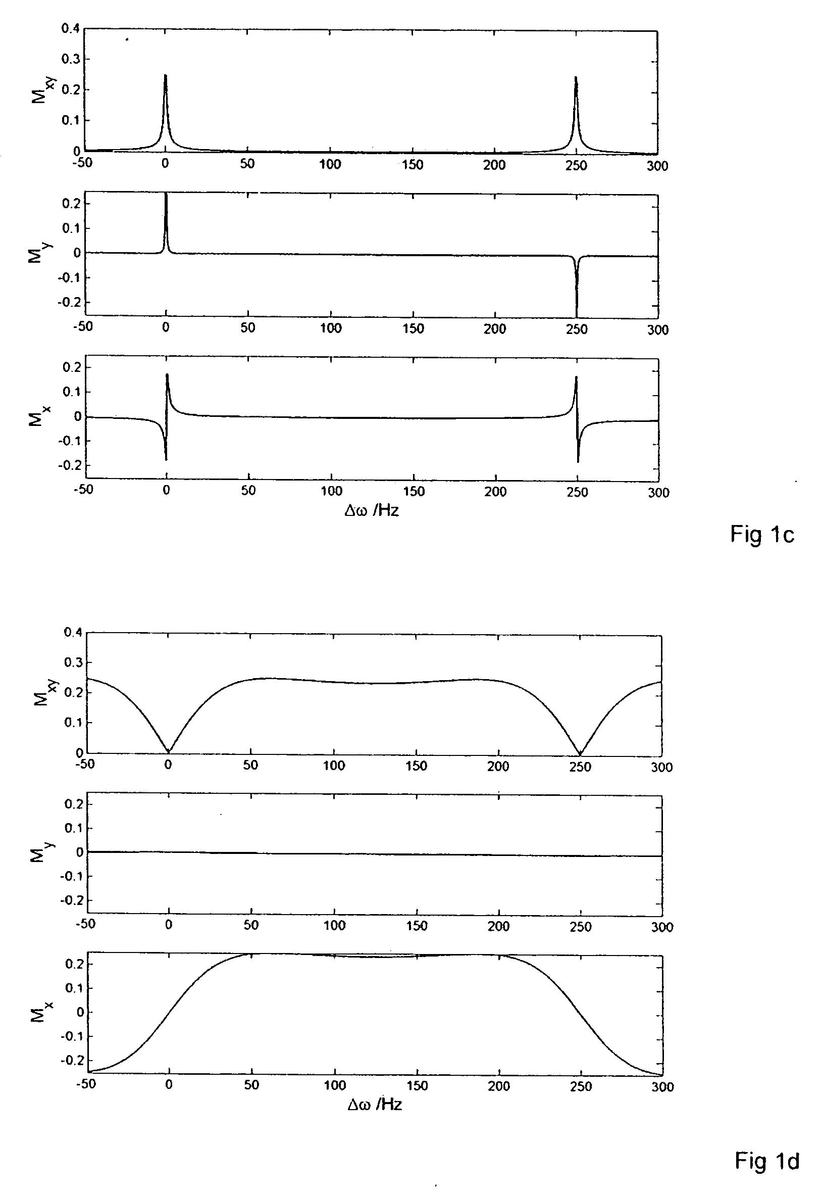
The present invention describes a magnetic resonance imaging method wherein spatially resolved frequency sensitive image data are collected by means of free precession sequences employing very small radio frequency (RF) excitation pulses per unit time which result in highly frequency selective steady-state signals dominated by linear properties of the system, for which the superposition principle holds. By appropriate linear combination of steady state signals of N different frequencies, N resonance lines can be acquired simultaneously. This method allows spectroscopic recordings with very low RF power deposition which renders the method suitable for applications at high static magnetic field strengths.

Description


Claims


Application Information

Patent Timeline
Owner UNIV ZURICH
Learn More