
Measuring soil permeability in situ

a technology of soil permeability and in situ measurement, applied in the field of soil improvement, can solve the problems of large settlement, difficult to measure, and take years to occur

Inactive Publication Date: 2006-03-02
NILEX CONSTR
View PDF5 Cites 13 Cited by
  • Summary
  • Abstract
  • Description
  • Claims
  • Application Information

AI Technical Summary

Benefits of technology

[0016] Installation of the section of drain and tube combination is generally carried out by intruding the section of drain with the attached tube into the soil with a surrounding mandrel as taught for example in U.S. Pat. No. 5,213,449, which teaches standard installation of prefabricat...

Problems solved by technology

When loads are placed on the surface of soft, saturated clay deposits, large settlements often result because of compression of the clay material.
If the permeability (hydraulic conductivity) of the compressible soil is very low, this process takes place very slowly.
Total settlements of several meters are common and often take years to occur.
Such samples are obtained by techniques that disturb or remold the soil to the least extent possible.
Soil is more often than not very heterogeneous and the sample taken may not faithfully represent the gross characteristics of the soil.
Determining horizontal permeability in the laboratory involves expensive, nonstandard tests, which are rarely performed.
Such remolding can significantly affect soil permeability in the remolded area.
Attempts have been made to quantify this effect and correlate it with the laboratory-determined permeability; these have not been completely satisfactory.
Consolidation tests are expensive and time-consuming.

Method used


Image

  • Measuring soil permeability in situ
  • Measuring soil permeability in situ
  • Measuring soil permeability in situ

Examples


Embodiment Construction

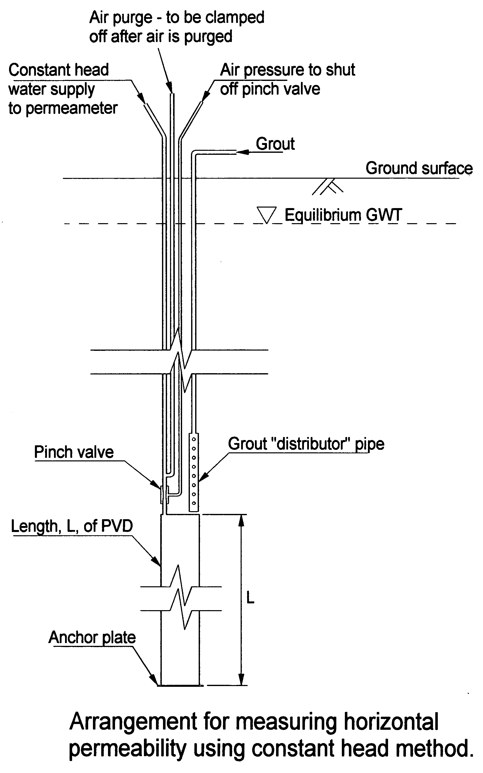
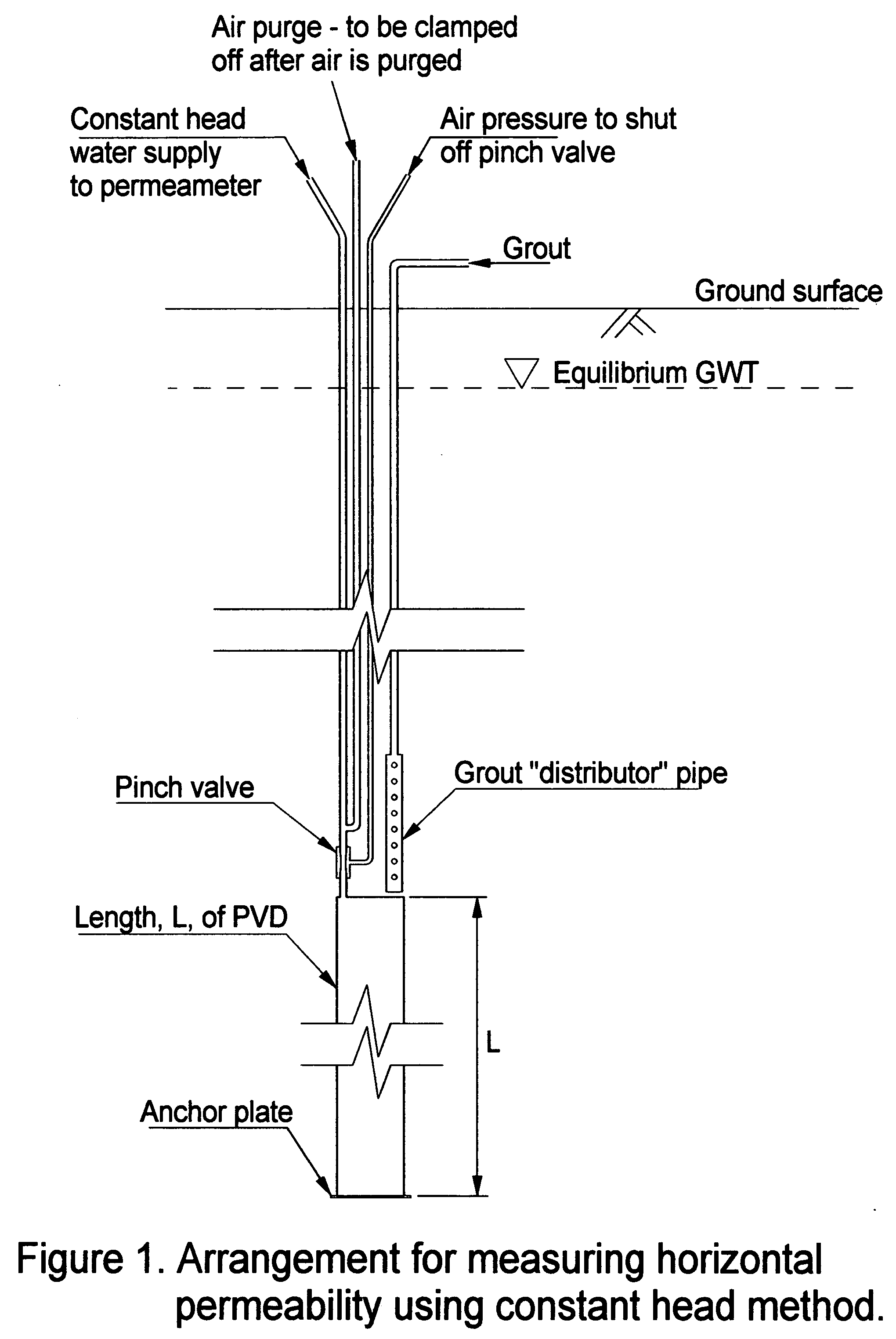
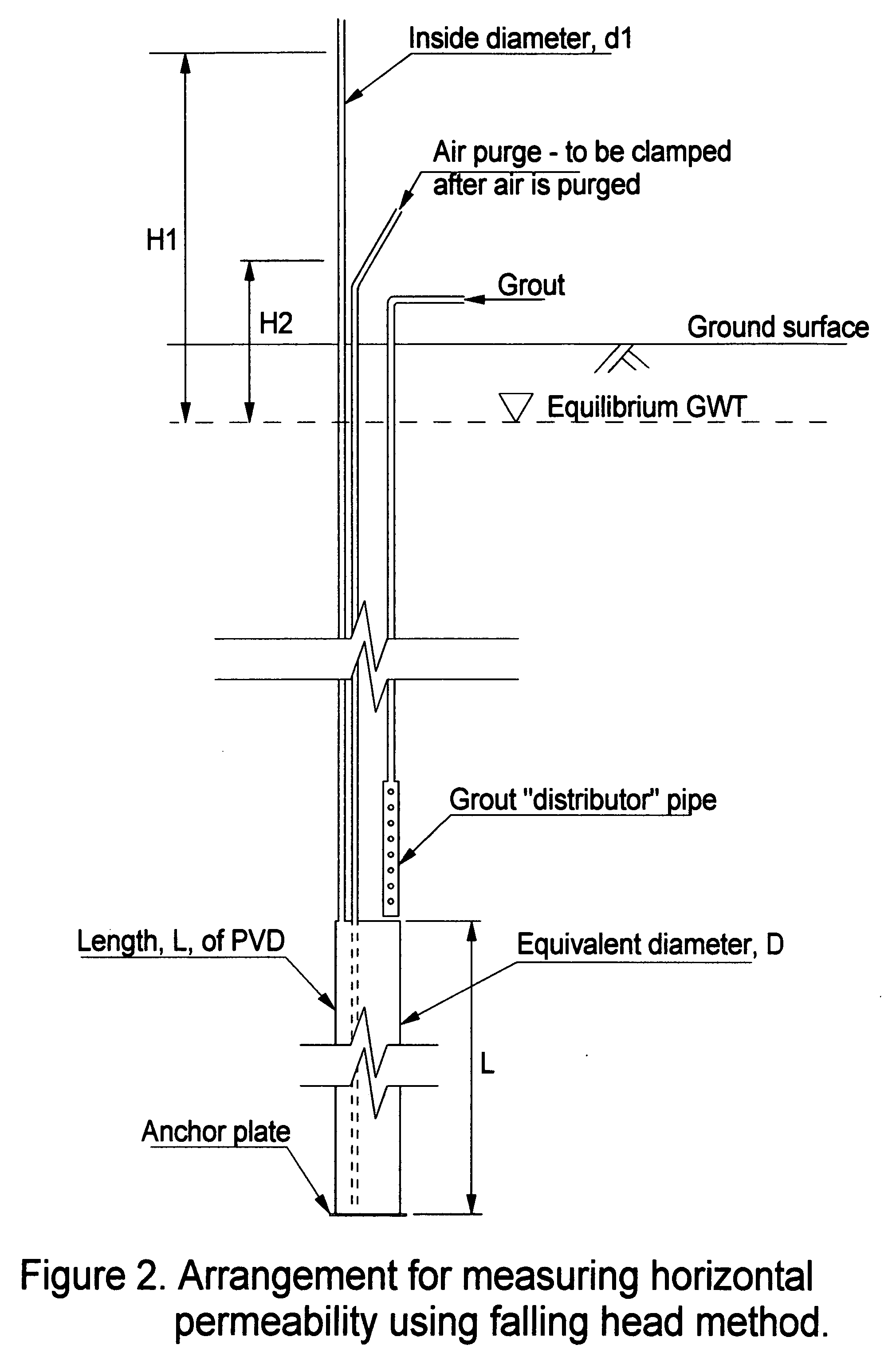
[0021] Presented here is a method that provides a measure of soil permeability in situ, and under installation and operating conditions, as they will exist for actual wick drain installations. The test apparatus consists of a length of wick drain material embedded in the ground at the depth under consideration. Tubes and pipes extend from the drain to the ground surface (see FIGS. 1 and 2).

[0022] This assembly is installed in the ground with the drain installation rig, using the same mandrel, anchor plate and installation procedures as will be used on the actual project. The drain test assembly is inserted into the mandrel on the installation rig with the anchor plate attached to the PV drain. The anchor plate will serve to cover the bottom of the mandrel preventing soil from entering the mandrel during penetration, and will anchor the test drain in place. The mandrel is then intruded by the machine into the ground to the desired depth, and withdrawn leaving the length, L, of wick ...


PUM


Abstract

Soil permeability is measured in situ by connecting an elongated fluid supply tube to a section of prefabricated vertical drain for remote fluid communication with interior portions of the drain. The combination drain with attached tube is then installed into the soil at a predetermined level below the soil surface with a proximal end of the tube exposed above the soil surface. The tube is then filled with water and the hydraulic conductivity of water in the tube and drain section combination is measured versus time for thereby measuring the soil permeability in situ.

Description

BACKGROUND OF THE INVENTION [0001] This invention relates generally to soil improvement, and more particularly to improvements in determining soil permeability, or hydraulic conductivity, as it relates to the installation and operation of vertical prefabricated drains used for consolidation acceleration, liquefaction mitigation, remediation and contaminant removal. [0002] When loads are placed on the surface of soft, saturated clay deposits, large settlements often result because of compression of the clay material. In saturated material, this settlement can take place only as pore water is expelled. If the permeability (hydraulic conductivity) of the compressible soil is very low, this process takes place very slowly. Total settlements of several meters are common and often take years to occur. This time-dependent process is called consolidation. A process called sand drains and surcharging has been used in these cases since the 1920's (See D. E. Moran, U.S. Pat. No. 1,598,300). [0...

Claims


Application Information

Patent Timeline
IPC IPC(8): G01N15/08
CPCG01N15/0826E02D1/06
Inventor GOUGHNOUR, R. ROBERT
Owner NILEX CONSTR
Learn More