Shoelace tightening device

a shoelace and tightening technology, applied in the direction of shoelace fastening, shoelace fastening, footwear, etc., can solve the problems of difficult tying or untying action of the shoelace, the inability to ensure that the shoelace is tightened with a constant tension, and the drawbacks of shoelace-type shoes, so as to facilitate the wearer to quickly tighten or loosen the shoela

Inactive Publication Date: 2006-03-02
MIN DUCK GI
View PDF4 Cites 3 Cited by
  • Summary
  • Abstract
  • Description
  • Claims
  • Application Information

AI Technical Summary

Benefits of technology

[0005] Therefore, the present invention has been made in view of the above problems, and it is an object of the present invention to provide shoelace tightening devices for making it easier for the wearer to rapidly tighten or loosen shoelaces of shoelace-type shoes, such as sports shoes, whenever putting on or taking off the shoes.

Problems solved by technology

Such shoelace-type shoes, however, have several drawbacks due to the fact that the wearer has to tie or untie the shoelace whenever putting on or taking off the shoe.
That is, it is actually impossible to ensure that the shoelace are tightened with a constant tension, and the tying or untying action of the shoelace may be difficult for some wearers, and requires a relatively long time.
Further, hanging ends of the shoelace, which remain after tying, may result in a low wearing comfort upon fluttering.

Method used


Image

  • Shoelace tightening device
  • Shoelace tightening device
  • Shoelace tightening device

Examples


Embodiment Construction

[0012] Now, preferred embodiments of the present invention will be explained in detail with reference to the accompanying drawings.

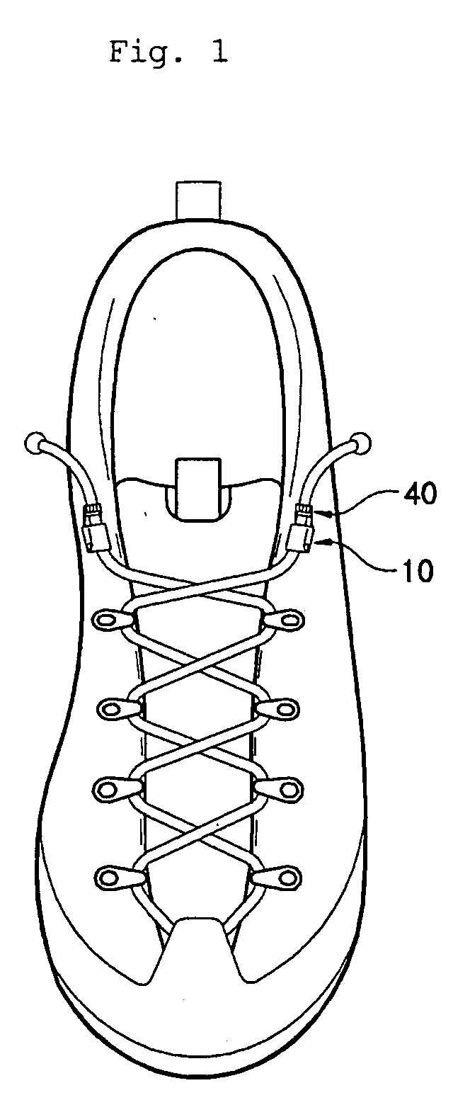
[0013] Considering first a general shoelace tying manner, both ends of a shoelace alternately pass through a plurality of lace loops arranged along an eyelet line defined at the top of a shoe so as to crisscross each other. After being completely tied, both the ends of the shoelace are appropriately tightened so as not to be unintentionally untied from the shoe by making use of a pair of shoelace tightening devices according to the present invention. Hereinafter, since the pair of shoelace tightening devices are identical to each other, only one of the devices will be explained.

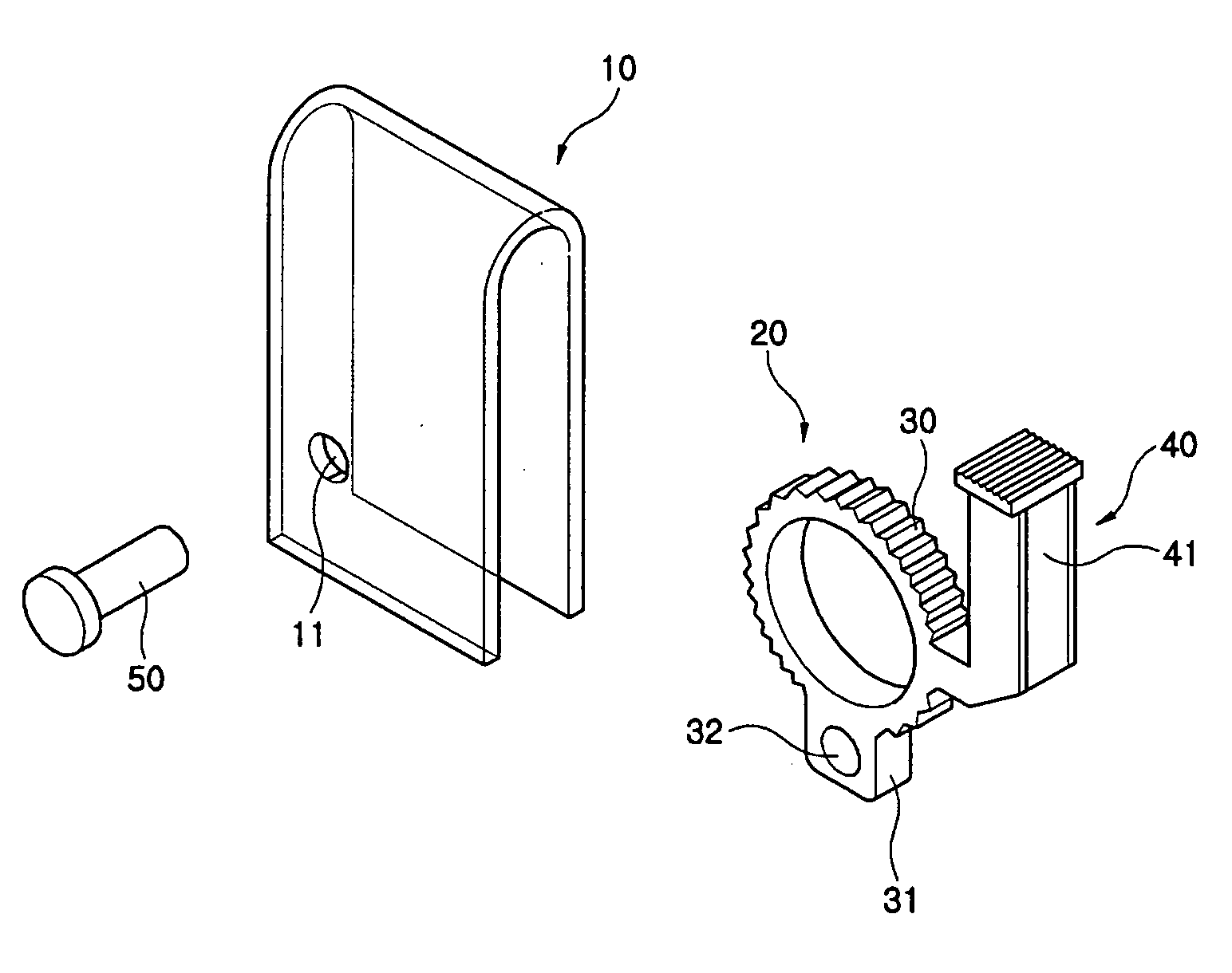
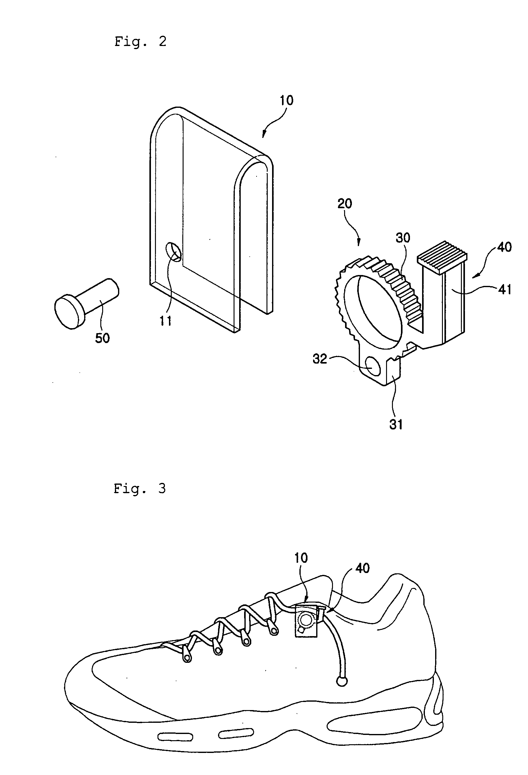
[0014]FIG. 2 illustrates the configuration of the shoelace tightening device according to the present invention. As shown in FIG. 2, the shoelace tightening device comprises: a cover 10, a tightening unit 20 rotatably inserted in the cover 10, and a fixing pin 50 for coupling th...


PUM


Abstract

Disclosed herein is a shoelace tightening device for shoelace-type shoes, including sports shoes. The device, for tightening a shoelace tied through a plurality of loops arranged along an eyelet line defined at the top of a shoe to form crisscross patterns, comprises a cover opened at a lower surface and opposite lateral surfaces thereof to have an inverted U-shaped cross section, and having a pair of pin-holes centrally perforated through plate shaped front and rear pieces thereof, a tightening unit rotatably inserted in the cover, and a fixing pin for coupling the cover and the tightening unit to each other. The tightening unit includes an annular toothed portion formed at an outer circumference thereof with a plurality of teeth, a support portion integrally connected to a bottom position of the outer circumference of the annular toothed portion and perforated with a fixing hole, and a button portion integrally connected at a lower end thereof to a lateral center position of the outer circumference of the annular toothed portion and laterally perforated with a shoelace guiding hole for guiding the drawing of the shoelace. A tip end of the fixing pin is fixed above the eyelet line. With such a configuration, a pair of the shoelace tightening devices of the present invention, fixed at opposite side positions above the eyelet line of the shoe, make it easier for the wearer to rapidly and simply tighten or loosen the shoelace of the shoe, resulting in an enhanced convenience in putting on or taking off the shoe.

Description

[0001] This application claims priority to Korean Patent Application No. 20-2004-24312 filed Aug. 25, 2004. TECHNICAL FIELD [0002] The present invention relates to shoelace tightening device, and more particularly, to shoelace tightening device for making it easier for the wearer to rapidly tighten or loosen shoelaces of shoelace-type shoes, such as sports shoes, whenever putting on or taking off the shoes. BACKGROUND ART [0003] Generally, most widely used sports shoes are designed to enable the wearer to tighten his / her shoe to conform closely with the overall shape of the wearer's foot by using a shoelace, except for some shoes using velcro-fasteners. [0004] Such shoelace-type shoes, however, have several drawbacks due to the fact that the wearer has to tie or untie the shoelace whenever putting on or taking off the shoe. That is, it is actually impossible to ensure that the shoelace are tightened with a constant tension, and the tying or untying action of the shoelace may be diff...

Claims


Application Information

Patent Timeline
Patent Type & Authority Applications(United States)
IPC IPC(8): A43C7/08
CPCA43C7/00Y10T24/3713A43C7/08A43C11/12
Inventor MIN, DUCK-GI
Owner MIN DUCK GI
Why Eureka
Try Eureka