
Steam generating device and iron using the steam generating device

a technology of steam generating device and steam generating device, which is applied in the direction of mechanical equipment, lighting and heating equipment, and discharging methods of containers, etc., can solve the problems of limited operation time, inconvenient, and inability to produce vertically continuous steam, etc., and achieve the effect of efficient operation

Inactive Publication Date: 2006-01-19
FUNG KAI TUNG AUGUSTINE
View PDF9 Cites 33 Cited by
  • Summary
  • Abstract
  • Description
  • Claims
  • Application Information

AI Technical Summary

Benefits of technology

[0012] An object of the present invention is to provide a steam generating device that is simple in structure, low in cost, and capable of providing steam continuously and fully.
[0014] A further objective of the present invention is to provide a steam iron when used with a steam generating device which allows clothes to be ironed continuously with the iron needing substantially no time for an operating condition to be reached. Thus, the iron can be operated efficiently such that it substantially replicates the capacity of a boiler with respect to steam generation.

Problems solved by technology

The first type includes irons having a small water container and which cannot produce vertically continuous steam.
This limited operation time is not convenient and steam cannot be supplied immediately and thus, is inefficient.
However, these types of irons are only suitable for use in large-scale clothing factories since they are prohibitively costly and inconvenient for use in residential households due to their large size and heavy components.

Method used


Image

  • Steam generating device and iron using the steam generating device
  • Steam generating device and iron using the steam generating device
  • Steam generating device and iron using the steam generating device

Examples


Embodiment Construction

[0027] The detailed description of the preferred embodiment of the present invention shall be described hereinafter with reference to the drawings wherein like numerals represent like parts throughout the views.

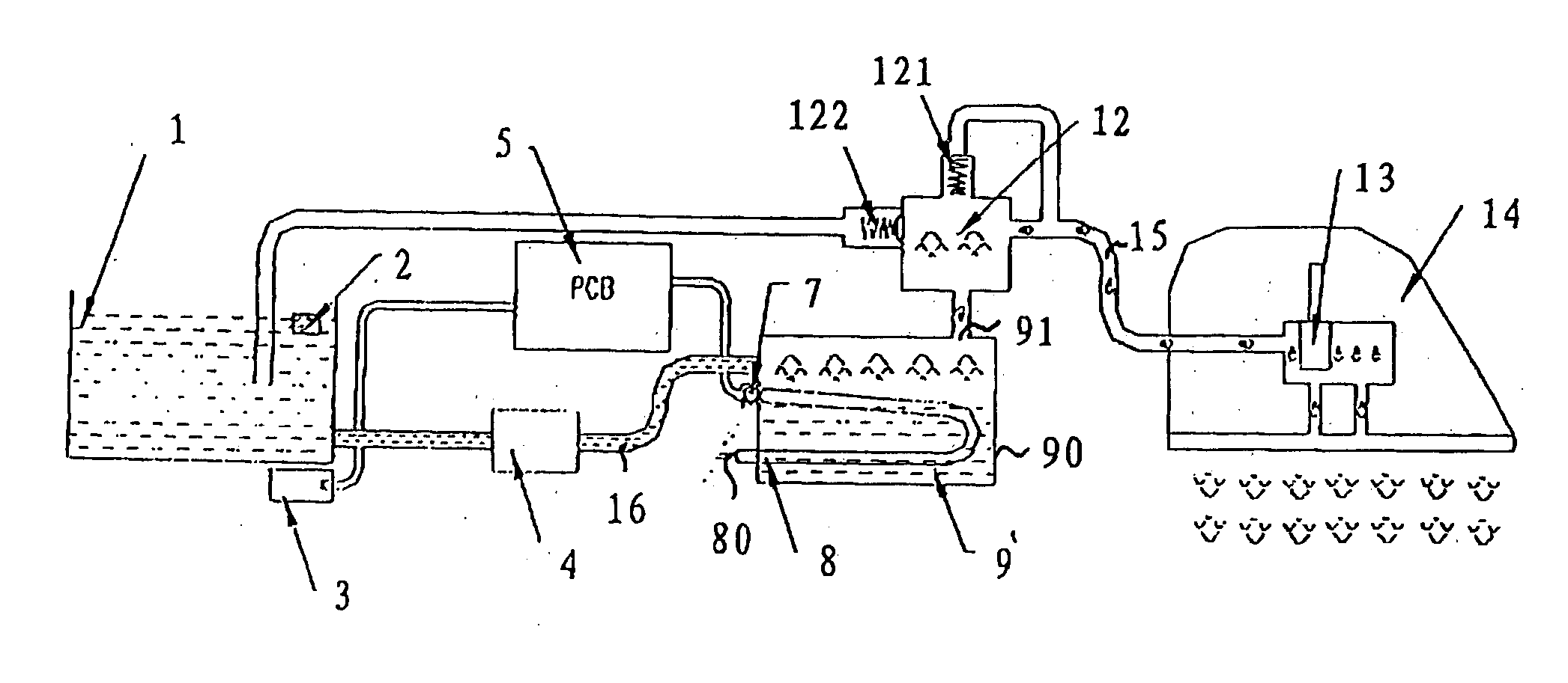
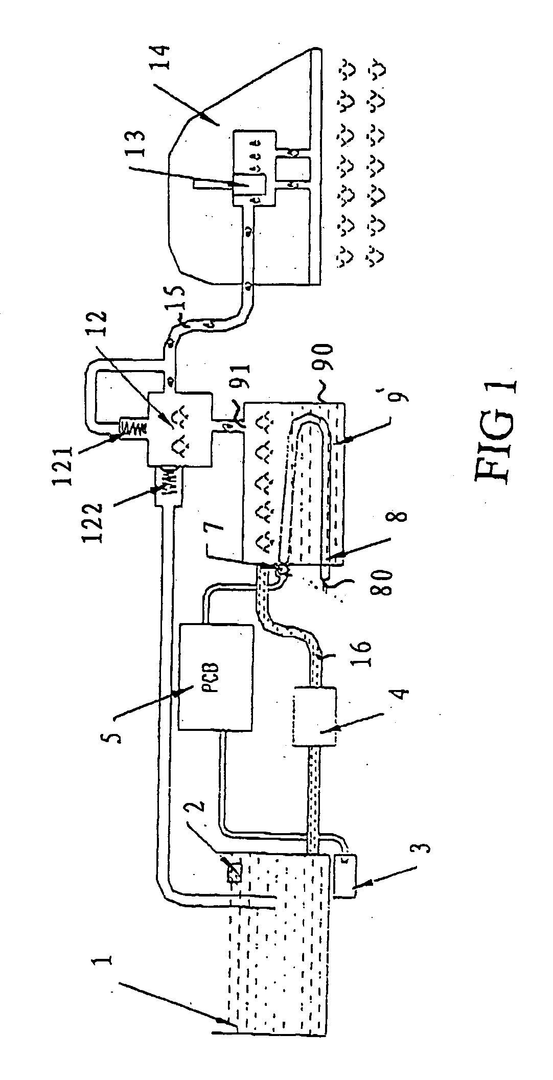
[0028] In one embodiment of the invention, as shown in FIGS. 1 to 3, the steam iron system in the present invention includes a steam generating device 9 and a steam iron 14. The steam generating device 9 and the steam iron 14 are connected by a tube 15 attached to a four-way electromagnetic valve 12. The steam generating device 9 is connected to a cold water container 1 via a second tube 16. The second tube 16 may be connected to a pump 4 such that the pump is intermediate the ends of the second tube 16. A float valve 2 is installed inside the cold water container 1. Located underneath the float valve 2 is a magnetic switch 3. It should be noted that in one embodiment of the invention, the cold water container 1 can be replaced by a water pipe and the float valve 2 and the m...


PUM


Abstract

The present invention discloses a steam generating device comprising a control circuit for monitoring the temperature and controlling water filling and heating and steam discharging, and a sealed container which is highly temperature resistant. An electric heating tube is mounted in the container and a temperature sensor is mounted on the outer surface of the container. The electric heating tube and the temperature sensor are connected respectively to the control circuit. On the top of the container there is installed a four-way electromagnetic valve, and on the wall of the four-way electromagnetic valve there is installed a water intake tube connected to a water supply. A steam iron using the steam generating device is also disclosed in the present invention, wherein the steam iron can be used together with the steam generating device and has the virtue of continuous water filling steam generation.

Description

FIELD OF THE INVENTION [0001] The present invention generally relates to steam generating devices. In particular, the present invention relates to steam generating devices for use with associated irons. BACKGROUND OF THE INVENTION [0002] Typically, steam irons that are used in residential households, clothing stores, and / or clothing factories can be categorized into three types. The first type includes irons having a small water container and which cannot produce vertically continuous steam. The second type includes irons suitable for use in households and which has an embedded water container. This second type of iron can only be used for a limited period of time, after which time the water container must be filled. The water container cannot be filled while the iron is in operation. This limited operation time is not convenient and steam cannot be supplied immediately and thus, is inefficient. [0003] The third type of irons include those suitable for use in clothing factories. Thi...

Claims


Application Information

Patent Timeline
IPC IPC(8): D06F75/12
CPCD06F75/12F22B1/285D06F75/20
Inventor FUNG, KAI TUNG AUGUSTINE
Owner FUNG KAI TUNG AUGUSTINE
Learn More