
Adapter and its use

a technology of adapter and adapter, which is applied in the field of adapters, can solve the problems of unambiguous control of liquid draining through the connection means, easy spillage of liquid, and the ineffectiveness of the means in the device for opening the take-out valv

Inactive Publication Date: 2005-12-08
PI-DESIGN AG
View PDF18 Cites 20 Cited by
  • Summary
  • Abstract
  • Description
  • Claims
  • Application Information

AI Technical Summary

Benefits of technology

[0010] Thus the risk that a force contribution from even a high level of a column of heavy liquid can press the adapter out of the outlet area of the container in the moment of the most critical force related situation, where the adapter is getting removed from the device, inter alia overcoming the sealing forces at the connection port, is avoided; the size of the container will often promote the container body and not the adapter body being influenced by the external force for the removal of the adapter plus container from the device; the attachment means are able to provide a heavy sealing grip between the container and the adapter. Thereby it is avoided that the adapter remains connected to the device, while the container is being removed from the adapter with probably waste of liquid as a consequence.
[0011] Preferably the attachment means having contact with the drain opening wall consists of an elastomer. The attachment means can hereby easier take up irregularities and dimension tolerances in the outlet area of the container and secure a safer sealing; at the same time there will be no requirement for a sealing elasticity of the container's material round the outlet area.
[0013] Preferably the overall truncated cone detailed can have a towards the tapered end constantly stepped form substantially shaped as successively alternating adjacently placed circumferential ribs and grooves with constantly decreasing respective characterizing diameter to the tapered end. Thus a better defined force or sealing against the actual container's outlet area is achieved, as a rib with smaller diameter further inside the outlet area can execute the sealing function against the outlet area internal wall and other ribs of larger diameter can provide a heavy force contributing to the cohesiveness of the container and the adapter, even if the larger diameter material is stressed beyond its sealing limit and / or is only partly being in touch with the edge of the outlet area.
[0014] Preferably the flow conduit of the pressure equalizing valve can join to the flow passage immediately upstream of the take-out valve. Thus an adapter having an extreme short distance between the device and the container can be provided, so that a more stable stack can be achieved, when the container is only supported on the adapter placed in the deep hole of the device. Moreover a smaller overall dimension of the container and adapter combination can be realized, being beneficial e.g. during storing in confined volumes like refrigerators.
[0018] Preferably the elastomer of the attachment means can be shaped as a sleeve, which is mounted on a supporting, preferably tubular, structure of the adapter body, yielding an increased sealing force ability, because the backing tubular structure inside can brace the elastic sleeve.
[0020] Preferably the adapter's flow passage from the container to the device can be substantially linear, yielding possibility for optimal flow.

Problems solved by technology

The adapter according to WO98 / 20832 has the severe disadvantage that liquid draining through the connection means is not unambiguous controlled, when the adapter has been removed from the liquid demanding device, with the consequence, that liquid easily will be spilled.
This because the means in the devices for opening the take-out valve can only be effective, while that sealing is established.

Method used


Image

  • Adapter and its use
  • Adapter and its use
  • Adapter and its use

Examples


Embodiment Construction

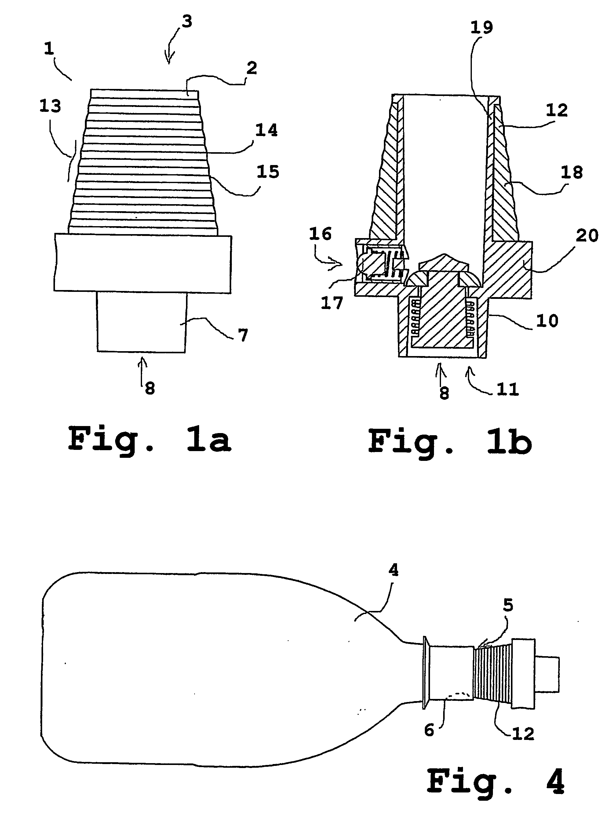
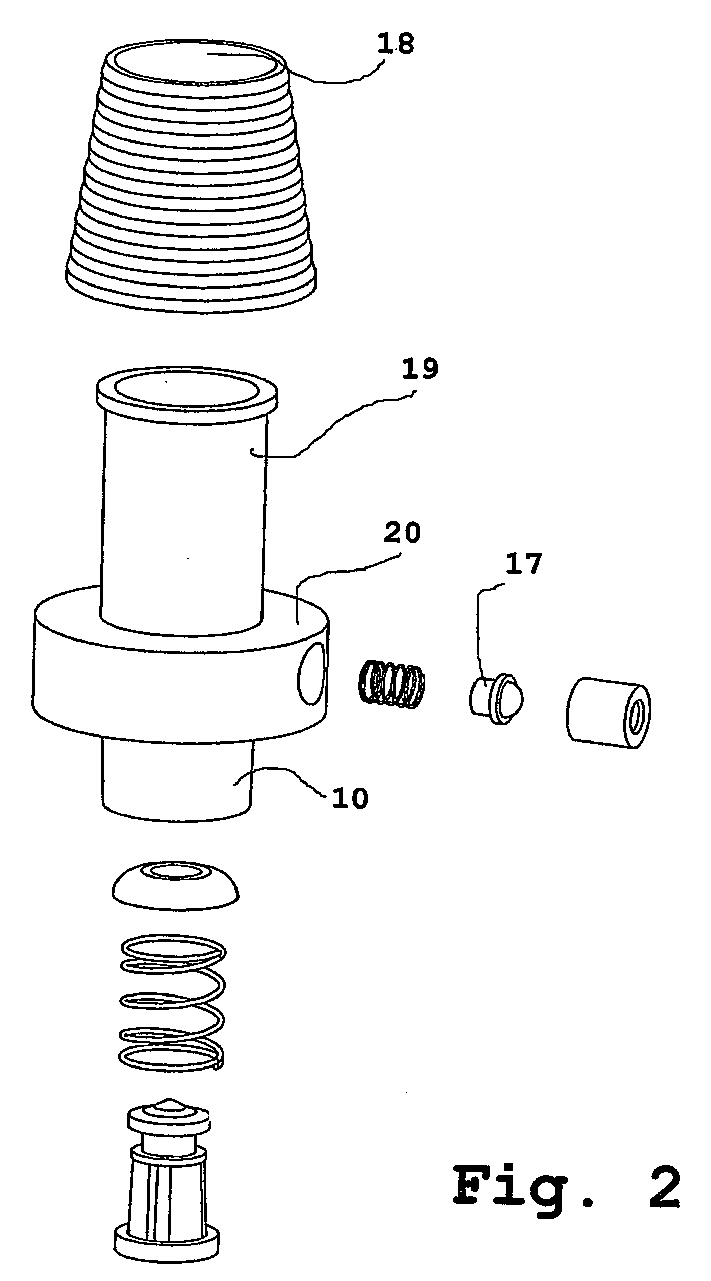
[0031] Reference is now made to the FIGS. 1a-4, wherein same reference numbers are used in all the figures for same or similar items.

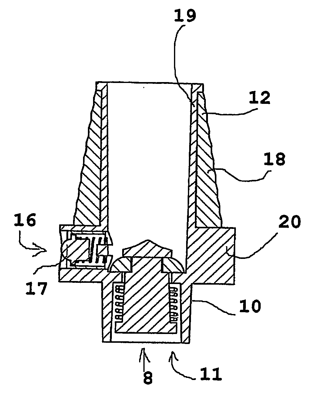
[0032]FIG. 1a shows a frontal elevation of a preferred embodiment of an adapter 1 according to the invention, the attachment means 2 pointing upwards. The attachment means 2 are configured as an attachment port 3 for a sealing, forced attack in the drain opening 5 outlet area of a container 4, e.g. a bottle (see FIG. 4: 4, 5, and 6). The lower part of the adapter 1 consists of connecting means 7 configured as a connection port 8, whose external part being prismatic or cylindrical for a telescoping fit in a corresponding deep hole of suitable profile depth in a receiving device 9 to yield a seal around the circumference of the prism or cylinder (FIG. 1b: 10) at telescoping placement of the connection port 8 in the deep hole at least some distance before reaching the bottom.

[0033]FIG. 1b shows the adapter 1 from FIG. 1a sectioned in its central plane p...


PUM


Abstract

An adapter connecting between a rigid container with one drain opening and a liquid demanding device, comprises one attachment port for sealing connection to the container's drain opening and a valve connecting to the flow-passage between the attachment port and connection means for the liquid demanding device, for equalizing pressure inside the container. Characterizing means are: attachment means (2) to keep a container sealingly attached in the drain opening; connection means (7) having externally a prismatic or cylindrical form (10) fitting in a corresponding deep hole in the device, wherein a sealing to the prism or cylinder's surface between the interior of the deep hole and the surroundings is established; and a take-out valve (11) in the flow direction in the connection port (8), being opened by means in the device (9) after sealing to the prism or cylinder (10) has been established. Easy connection to various containers and no spillage when not in use are the main benefits.

Description

FIELD OF THE INVENTION [0001] The present invention relates to an adapter and the use of same. PRIOR ART [0002] From WO98 / 20832 an adapter is known with respectively attachment and connection means to establish both physical fit and flow connection between: [0003] a container with one drain opening, otherwise closed—and being substantially rigid and [0004] an at least occasionally liquid demanding device, respectively. [0005] The attachment means comprise one attachment port for connection to the drain opening of at least one detachable, and possibly replaceable, container, with sealing properties compared to the surroundings, and a valve being placed in fluid connection with the flow passage between the attachment port and the connection means for the liquid demanding device for automatically equalizing pressure inside the container compared to the surrounding pressure substantially simultaneously with the devices' draining of liquid from an attached container of the type mentioned...

Claims


Application Information

Patent Timeline
Patent Type & Authority Applications(United States)
IPC IPC(8): A47J31/44A47J31/46A61J9/04B65D51/24B67D3/04F16K17/04F16K51/00
CPCA47J31/44F16K17/04B67D3/044A47J31/46
Inventor BODUM, JORGEN
Owner PI-DESIGN AG
Learn More