
Road traffic simulation apparatus

Inactive Publication Date: 2005-09-01
HONDA MOTOR CO LTD
View PDF5 Cites 56 Cited by
  • Summary
  • Abstract
  • Description
  • Claims
  • Application Information

AI Technical Summary

Benefits of technology

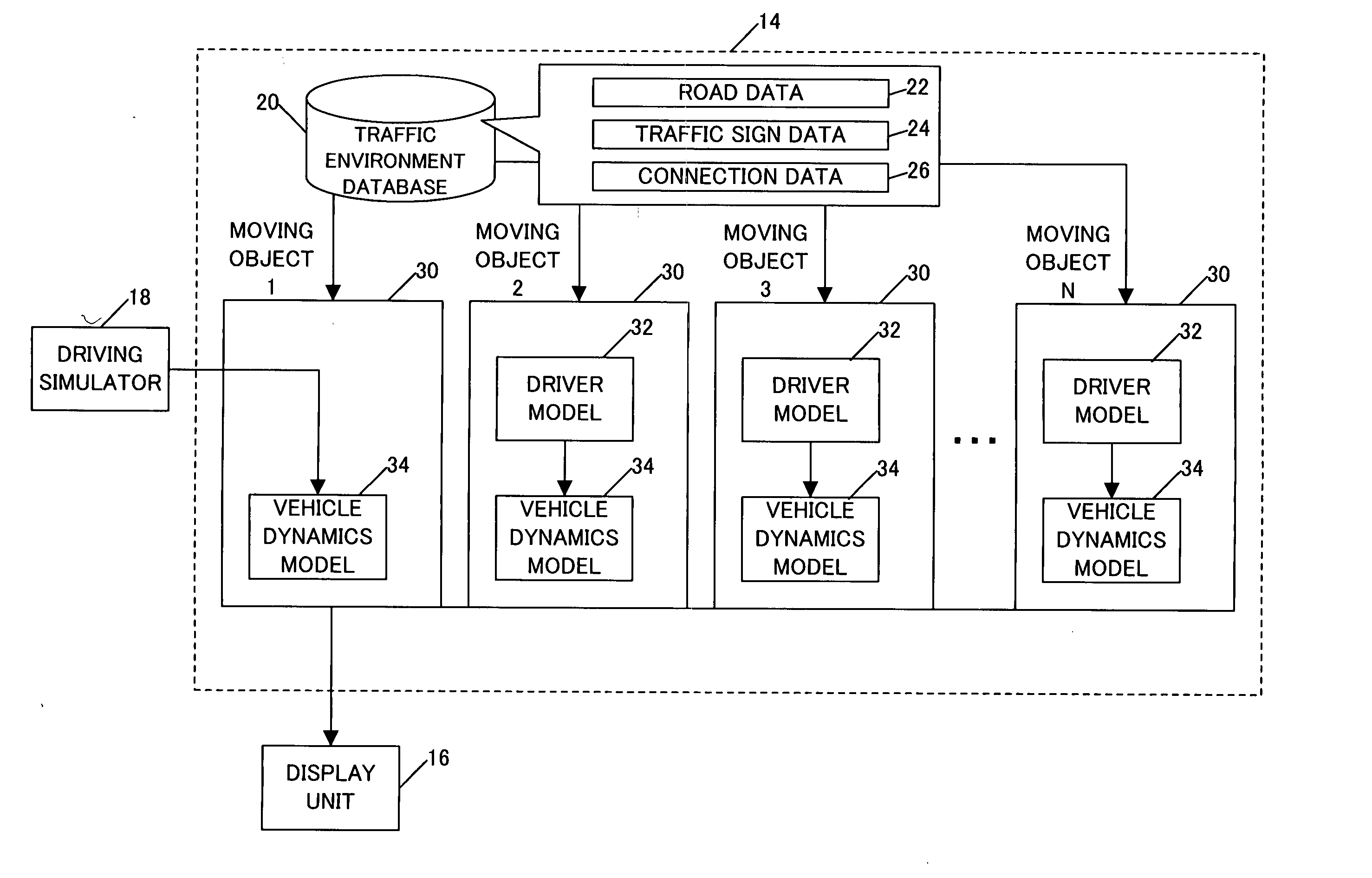
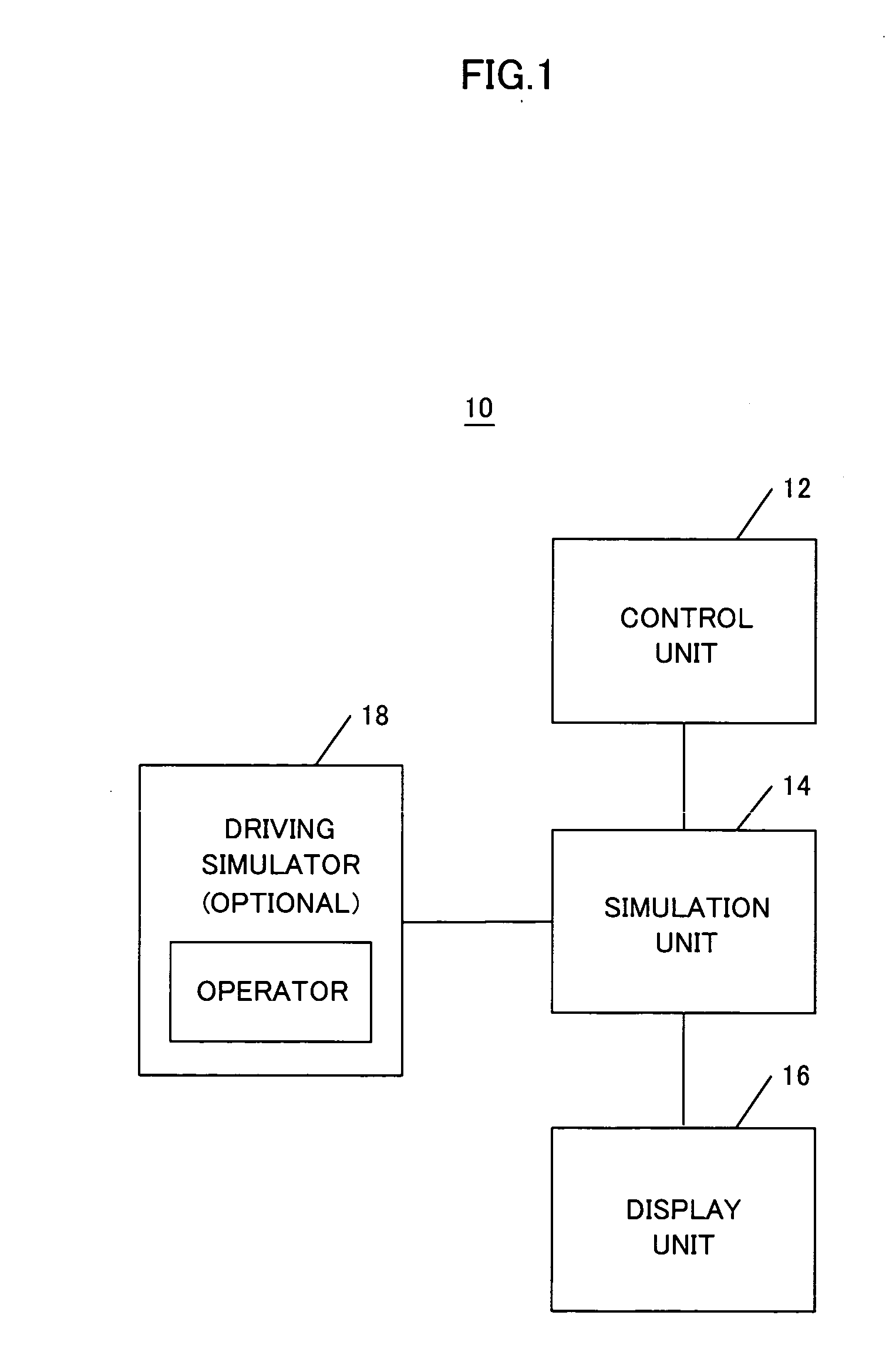
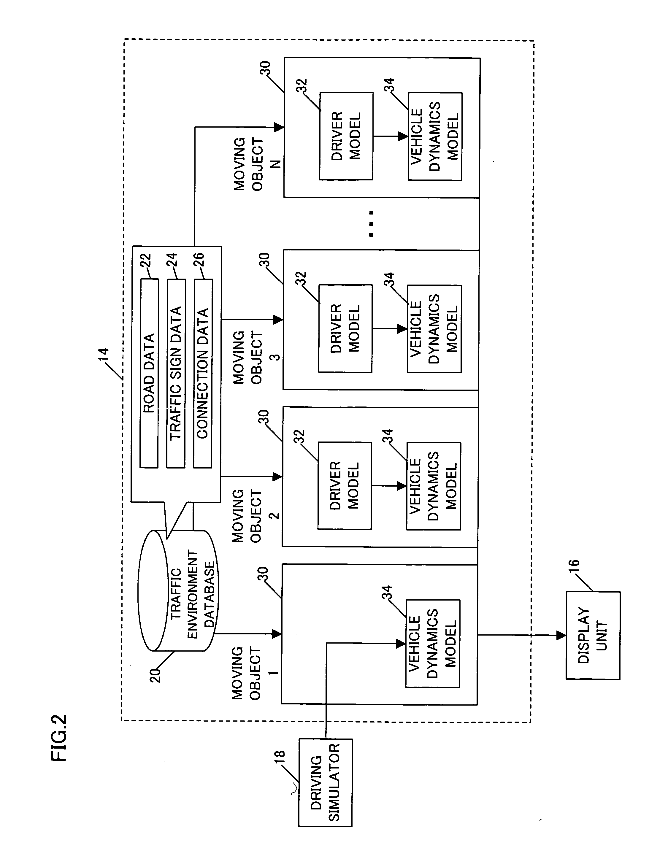
[0013] The present invention provides a road traffic simulation apparatus having a simulation unit for performing a traffic simulation, a display unit for displaying a progress status of the traffic simulation and a control unit for controlling the simulation unit. The simulation unit has a traffic environment database and a moving object model. The moving object model has a driver model in which a driving operation of a driver is modeled and vehicle dynamics model in which a vehicle behavior is modeled. The driver model performs different processes in parallel in respective different cycles.

Problems solved by technology

The travel difficulty is reflected in the driver's operation.
The travel difficulty is reflected in the driving operations.

Method used


Image

  • Road traffic simulation apparatus
  • Road traffic simulation apparatus
  • Road traffic simulation apparatus

Examples


second embodiment

2.2.9 Second Embodiment of Intermediate Cycle Process

[0127] The above-described embodiment for the intermediate cycle process is a process for determining in parallel the target direction and the target speed by generating the travel difficulty for both direction and speed through use of the TD areas produced by the integrating unit 66. On the other hand, a sequential process may be implemented as a second embodiment, where the target direction is first determined and then the target speed is determined based on the determined target direction. The difference from the driver model 32 in FIG. 5 is in that the structure from the integrating unit 66 up to the target speed determining unit 78 is changed from parallel to sequential. Therefore, the second embodiment will be described below with attention focused on this difference.

[0128]FIG. 18 shows functional blocks from the integrating unit 66 up to the target speed determining unit 78 in which the structure is changed from the functi...


PUM


Abstract

A technique for simulating natural behaviors of moving objects is provided. A road traffic simulation apparatus includes a simulation unit for performing a traffic simulation, a display unit for displaying a progress status of the traffic simulation and a control unit for controlling the simulation unit. The simulation unit has a traffic environment database and a moving object model. The moving object model has a driver model in which a driving operation of a driver is modeled and a vehicle dynamics model in which a vehicle behavior is modeled. The driver model performs different processes in parallel in respective different cycles. The results of each cycle process are integrated and output to the vehicle dynamics model.

Description

BACKGROUND OF THE INVENTION [0001] The present invention relates to a road traffic simulator for performing a simulation of road traffic by operating autonomously on a computer a virtual vehicle that simulates a real vehicle behavior in a simulated road environment. [0002] In a typical conventional micro traffic simulation apparatus, speed of a vehicle is calculated to update the location of the vehicle according to such detailed rules as: (1) when there is no other vehicle in front of the subject vehicle, the subject vehicle travels freely according to the speed set for the vehicle or the lane; (2) when there is another vehicle, an obstacle or a traffic signal in front of the subject vehicle, the subject vehicle accelerates, decelerates or stops in accordance with the speed or distance relative to such an object before it; and (3) when making a turn, passing an obstacle or changing lanes, the subject vehicle takes a predetermined behavior as long as the relation with the opposite v...

Claims


Application Information

Patent Timeline
Patent Type & Authority Applications(United States)
IPC IPC(8): G08G1/00G09B9/05G09B19/16G09B23/00
CPCG09B9/05G09B23/00G09B19/167
Inventor SAWADA, YASUHIROKURODA, MITSUHIDE
Owner HONDA MOTOR CO LTD
Learn More