
Method and apparatus for the disposal of waste fluids

a technology of waste fluid and apparatus, applied in the direction of suction drainage containers, couplings, separation processes, etc., can solve the problems of increasing the cost of medical waste removal, increasing the cost of such removal, and the method also works

Active Publication Date: 2005-08-25
ALLEGIANCE CORP
View PDF37 Cites 53 Cited by
  • Summary
  • Abstract
  • Description
  • Claims
  • Application Information

AI Technical Summary

Benefits of technology

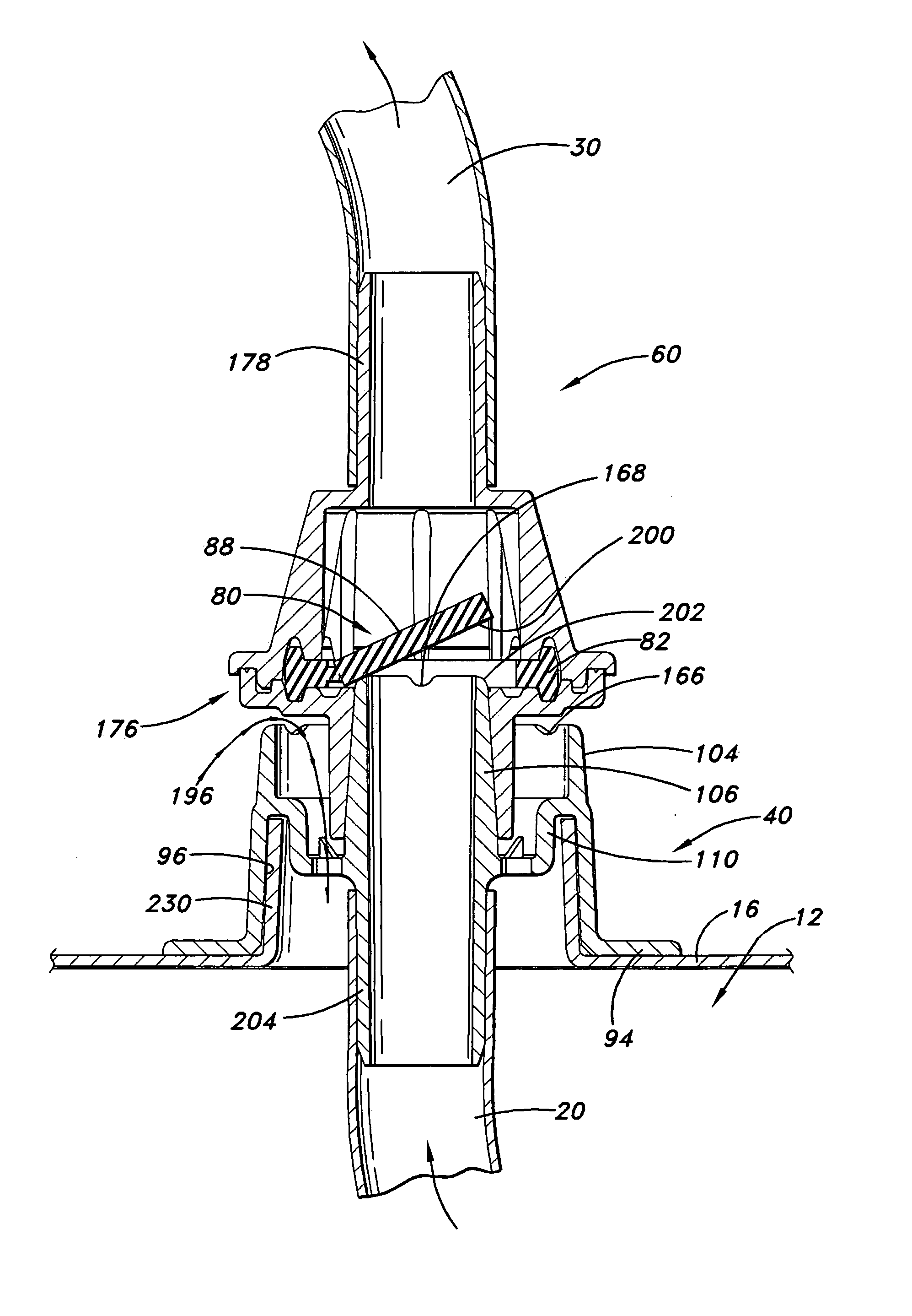
[0013] According to another aspect of the invention, the first connector which is attached to the second end of the first conduit includes an outer wall and an inner wall, both of which are generally cylindrical. An inner support member is disposed between the inner and outer walls and thereby joins them into an integral member. Holes located in the inner support member enable pressure on one side of the connector to be equalized with pressure on the other side of the connector.

Problems solved by technology

While this method works well for its intended purpose, medical waste removers typically charge by the weight of material being disposed.
Thus, including the collected fluids along with the container increases the cost of such removal.
This method also works well for its intended purpose but also is relatively expensive because the solidified fluids are still a significant portion (weight) of the waste to be disposed.
However, heightened awareness concerning employee safety makes this method less attractive.
Pouring of such waste fluids may disperse aerosols and may result in residual spilling and splattering of the waste fluids.
However, neither the Pinder nor Bemis assemblies have the advantages provided by the inventors of this patent.

Method used


Image

  • Method and apparatus for the disposal of waste fluids
  • Method and apparatus for the disposal of waste fluids
  • Method and apparatus for the disposal of waste fluids

Examples


Embodiment Construction

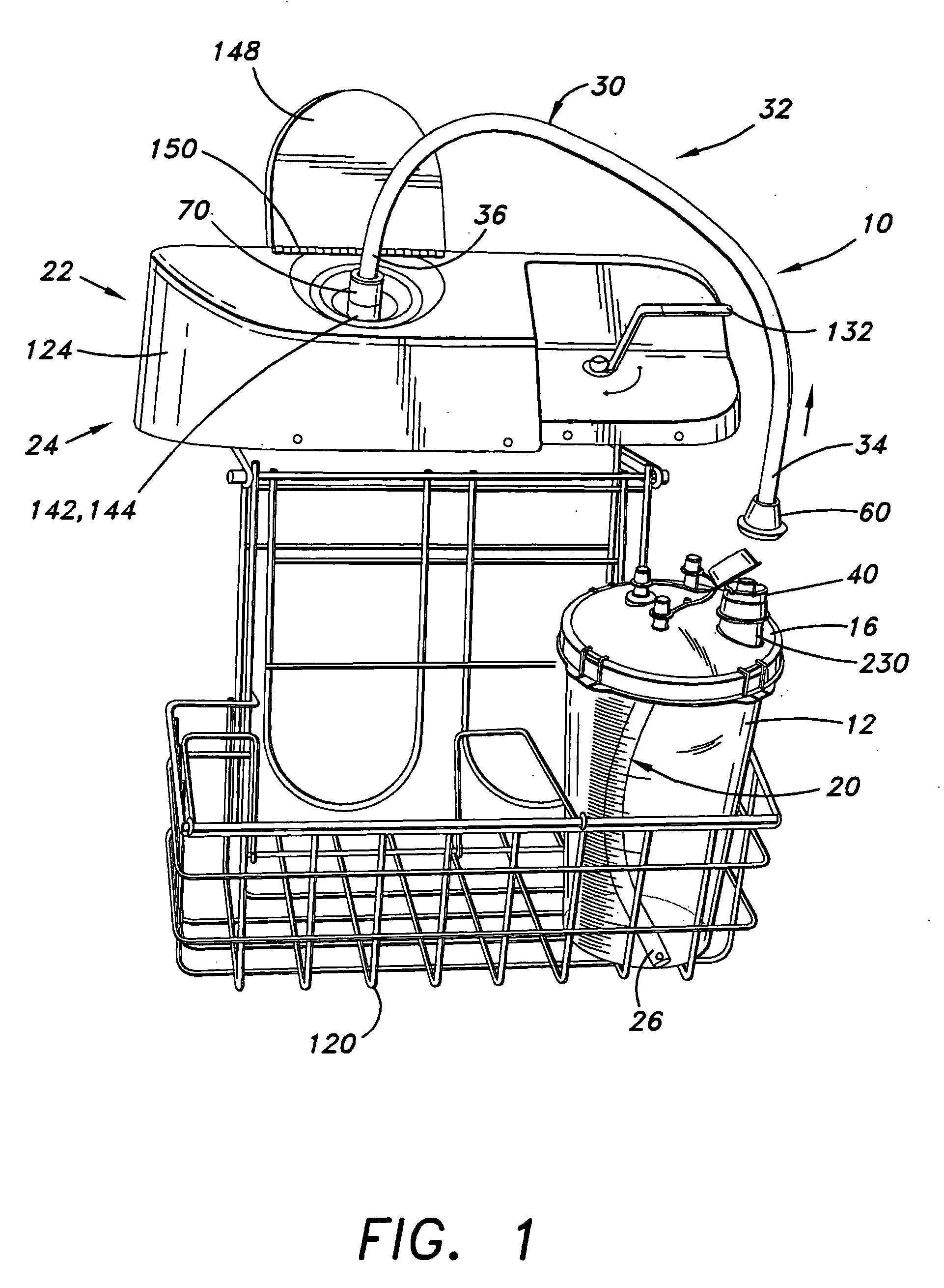
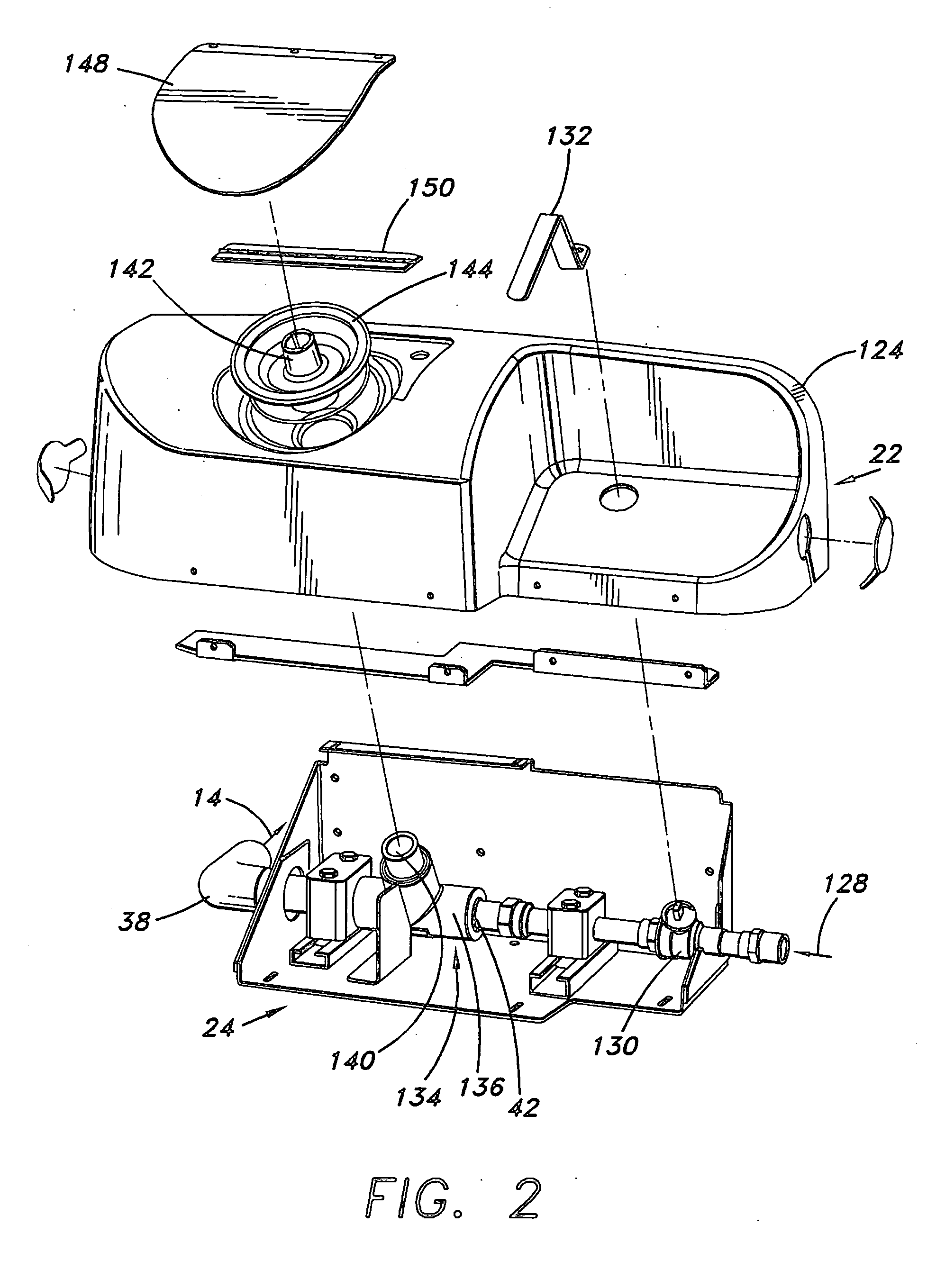
[0034] Referring now to the drawings wherein the showings are for purposes of illustrating a preferred embodiment of the invention only and not for purposes of limiting the same, FIG. 1 shows the inventive apparatus 10 that is used to remove waste fluid (not shown) from a canister or first receptacle 12. It should be noted that the inventive device will work with virtually any fluid, including fluids with certain solid matter mixed in. A cap 16 fits over the first receptacle 12 and operates as a lid. Preferably the cap 16 fits snuggly onto the top of the first receptacle 12 as is commonly known in the art. In the preferred embodiment, the first receptacle 12 sits in a wire basket 120. It is also preferred that the wire basket 120 is large enough to carry at least two first receptacles 12.

[0035] With reference now to FIGS. 2A, 2B and 2C, a typical first receptacle 12 and cap 16 is shown. Also shown is an optional, but standard, cap attachment 220. The cap attachment 220 shown includ...


PUM

PropertyMeasurementUnit
Lengthaaaaaaaaaa
Pressureaaaaaaaaaa
Flow rateaaaaaaaaaa

Abstract

An innovative method and apparatus for disposing of waste fluids, especially human body fluids such as are generated during surgery, into a hospital's sanitary sewer system is provided. A conduit system is adapted to transport waste fluid from a receptacle to a sanitary sewer using an eductor having a venturi device. The conduit system includes first and second conduits. First and second connectors are used to easily connect the first conduit to the second conduit. The second connector includes a flap that acts as a check valve.

Description

1. BACKGROUND OF THE INVENTION [0001] A. Field of Invention [0002] This invention relates to apparatuses and methods for disposing of waste fluids. More particularly, this invention relates to apparatuses and methods for disposing of waste fluids generated during medical procedures to a sanitary sewer. [0003] B. Description of the Related Art [0004] It is well known that blood, other body fluids and irrigating solutions must be removed from the body of patients when they undergo medical procedures, such as surgery. Medical providers, such as doctor's offices and hospitals, use a variety of different containers and apparatuses for collecting such fluids. These fluids must then be disposed of in an appropriate manner. [0005] Different methods of disposing of such fluids are known. One method is to dispose of the fluids and the container they are held in together as a unit. While this method works well for its intended purpose, medical waste removers typically charge by the weight of m...

Claims


Application Information

Patent Timeline
IPC IPC(8): A61M1/00B08B9/08F04F5/00F04F5/10
CPCA61M1/0001F04F5/10B08B9/08Y10T137/3185Y10T137/86075Y10T137/3294Y10T137/87619A61M1/882A61M1/60
Inventor MICHAELS, THOMAS L.HORTON, KENNETH JR.INGRAM, SHANNON C.
Owner ALLEGIANCE CORP
Learn More