Dew sensor

a technology of dew sensor and sensor body, which is applied in the field of dew sensor, can solve the problems of lowering the degree of detection accuracy, no appropriate light emitting element found up to now, and high power consumption, so as to increase the number of total reflections and enhance the detection accuracy. , the effect of increasing the number of repetitions

Inactive Publication Date: 2005-08-11
NILES PARTS CO LTD
View PDF25 Cites 15 Cited by
  • Summary
  • Abstract
  • Description
  • Claims
  • Application Information

AI Technical Summary

Benefits of technology

[0014] With the use of the reflection film provided in the part of the intermediate film, since the light beam travels in only one of the sheet glasses, the number of repetitions of total reflection is increased while the detection surface (in a zone in which a signal from the light receiving element varies when water drops stick to) is

Problems solved by technology

However, no appropriate light emitting element has been found up to now.
It may be contrived that the temperature characteristic is compensated with the use of a control circuit, but the detecting apparatus itself would become large-sized, resulting in high power consumption.
As a consequence, dew condensation on the surface of the windshield glass becomes different between the zone around the detecti

Method used


Image

  • Dew sensor
  • Dew sensor
  • Dew sensor

Examples


Embodiment Construction

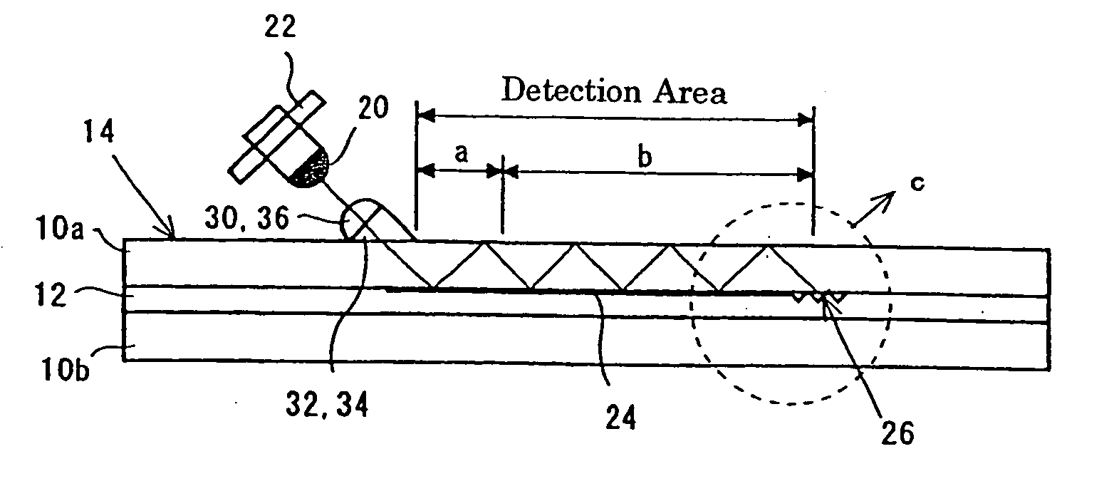
[0027] Referring to FIG. 1 which is a view for explaining an embodiment of a dew condensation detecting apparatus according to the present invention, there shows a basic configuration A as viewed in a section, a plan configuration B, and an enlarged view C of an essential part c in A. This dew condensation detecting apparatus comprises a laminated glass 14 composed of two sheet glasses 10a, 10b which are bonded to each other through the intermediary of an intermediate film 12, a light emitting element 20 and a light receiving element 22 which are arranged, proximate to each other, outside of the laminated glass 14 (the detection surface side: the upper surface in this embodiment), and a reflection film 24 and a micro-mirror array 26 which are provided in a part of the intermediate film 12.

[0028] A lens 30 for collimating a light beam from the light emitting element 20, and a light introducing prism 32 are located between the light emitting element 20 and a glass surface while a lig...


PUM

PropertyMeasurementUnit
Angleaaaaaaaaaa
Angleaaaaaaaaaa
Distanceaaaaaaaaaa

Abstract

A dew condensation detecting apparatus is independent of a wavelength of a detected light beam, and has a heat capacity of the detecting apparatus body so as to miniaturize the apparatus. A light beam is introduced from a light emitting element into the transparent plate and travels through the transparent plate with repetitions of total reflection. It is then detected by a light receiving element to detect a degree of dew condensation on a surface of the transparent plate in accordance with a variation in detected light quantity. The transparent plate is formed of two sheet glasses bonded to each other by an intermediate film, a part of which is a reflection film. A micro-mirror array for turn-back reflection, composed of oblique reflection surfaces inclined to the surfaces of the spaced sheet glasses, is provided near one end of the reflection film.

Description

TECHNICAL FIELD [0001] The present invention relates to a degree of dew condensation caused by water drops sticking to the outer surface of a glass with the use of a light beam introduced in a glass and traveling therethrough with repetitions of total reflection, and in particular to a dew condensation detecting apparatus in which a light beam is repeatedly reflected through turn-back by a micro-mirror array having a plurality of oblique reflection surfaces that are inclined to the glass surface and are spaced from one another. This technology is effective, in particular, for detecting dew condensation on the inner surface of a windshield glass of a vehicle on the passenger compartment side. However, it can be also applied for detecting water drops (rain drops) sticking to the outer surface of the windshield glass. BACKGROUND ART [0002] There have been already proposed and developed several technologies relating to an optical water drop detecting apparatus for detecting water drops ...

Claims


Application Information

Patent Timeline
IPC IPC(8): B60S1/08G01N21/17
CPCB32B17/10036B32B17/10174G01N21/552B60S1/0837B60S1/0877B60S1/0822G01N21/17B60S1/02
Inventor MURAKAMI, HARUNORIFURUSAWA, SATOSHISASAKI, MIKIO
Owner NILES PARTS CO LTD
Why Eureka
Try Eureka