Portable tool case and workstation
a tool case and workstation technology, applied in the field of tool cases, can solve the problems of inconvenience for users, inconvenient for handymen, and lack of flexibility in prior art tool cases
- Summary
- Abstract
- Description
- Claims
- Application Information
AI Technical Summary
Benefits of technology
Problems solved by technology
Method used
Image
Examples
first embodiment
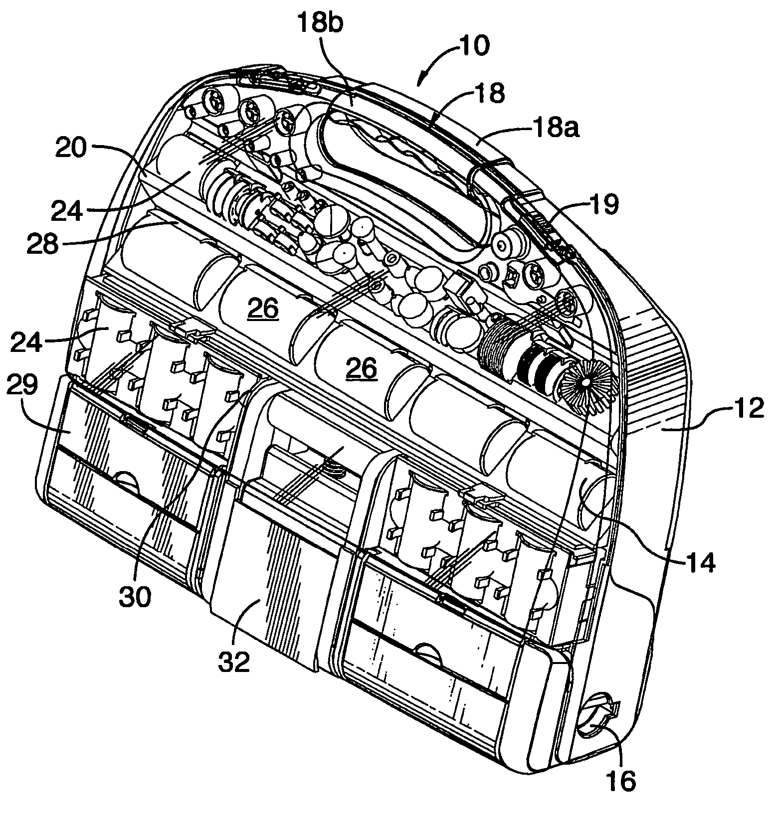
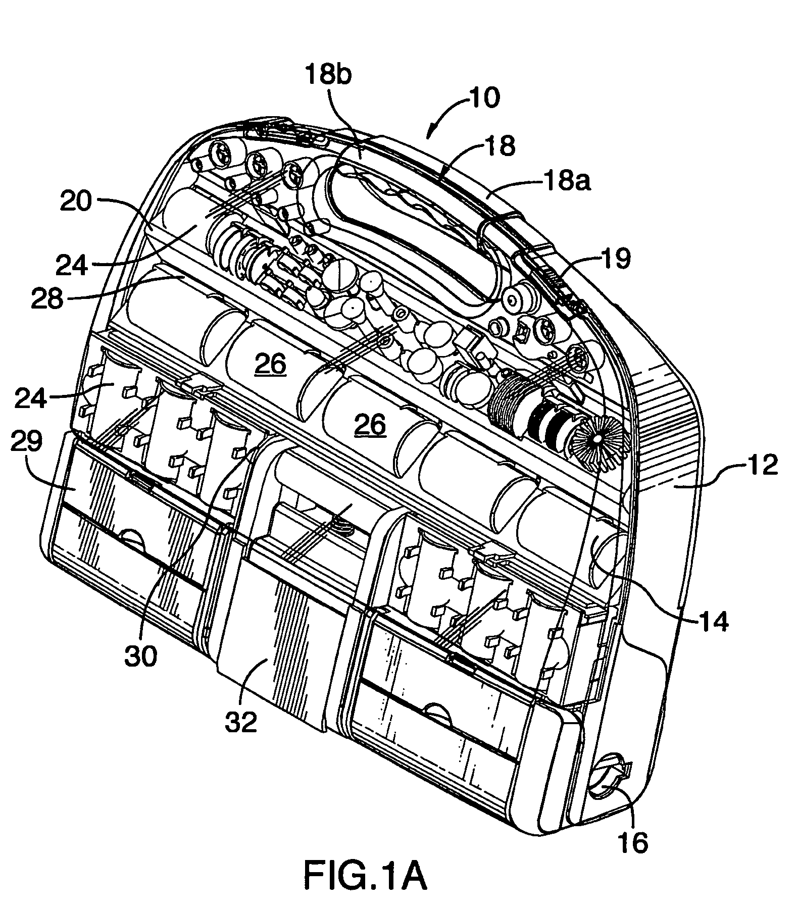
[0045] Referring to the drawings, FIG. 1A shows a tool case and workstation in a closed position. The tool case and workstation 10 has a base portion 12 and a lid portion 14. The lid portion 14 is attached to the base portion 12 by connecting means 16. In the present embodiment, the lid portion 14 is manufactured from a transparent plastic which allows the contents of the tool case and workstation 10 to be seen even when the tool case and workstation is in the closed position. Alternatively, the lid portion 14 may be manufactured from an opaque plastic. The base and lid portions 12 and 14 of the tool case and workstation 10 preferably have handles 18a and 18b, respectively, that complement each other to provide a carrying grip 18 for the user when the tool case and workstation 10 is in the closed position.
[0046] Locking means 19 secure the lid portion 14 to the base portion 12 in the closed position so that the tool case and workstation 10 cannot be inadvertently opened. In the pres...
second embodiment
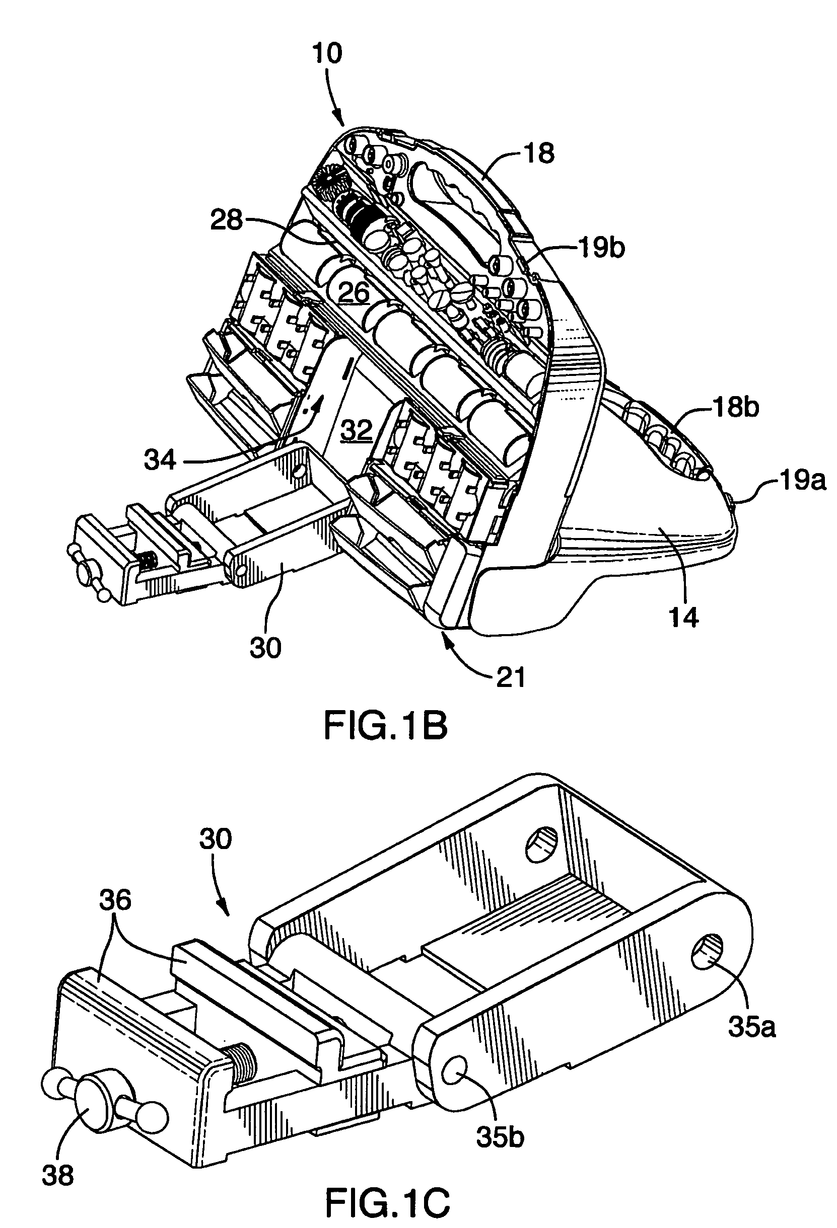
[0060] Turning to FIG. 1F, a workstation attachment 30 is shown. In this embodiment, when a grip 42 of the workstation attachment 30 is closed, the top edge of the grip 42 forms a groove 44, within which a complementary groove on the surface of the rotary tool 40 may be inserted in order to secure the rotary tool 40 in place.
third embodiment
[0061] Turning to FIG. 1G, a workstation attachment 30 is shown. In this embodiment, a groove 46 is formed on the top edge of one of the grips 48 which receives the rotary tool 40 in order to secure the rotary tool 40 in place.
[0062] Turning to FIG. 1H, a tool case and workstation is shown with a second type of workstation attachment. In FIG. 1H, the workstation attachment 49 is a universal holder with dovetail grooves. Similar to the vise described above, the workstation attachment 49 may be folded out from a storage position into an operational position so that a user may attach a tool to the workstation attachment 49, as shown in FIG. 1I. In FIG. 1I, an example of the workstation attachment 49 in use is shown with a rotary tool being attached to the universal holder. The rotary tool preferably has complementary dovetail grooves which mate with the dovetail grooves on the universal holder allowing for quick release and attachment of the tool to the workstation attachment. The work...
PUM
 Abstract
Description
Claims
Application Information
 - R&D
- Intellectual Property
- Life Sciences
- Materials
- Tech Scout
- Unparalleled Data Quality
- Higher Quality Content
- 60% Fewer Hallucinations
Browse by: Latest US Patents, China's latest patents, Technical Efficacy Thesaurus, Application Domain, Technology Topic, Popular Technical Reports.
© 2025 PatSnap. All rights reserved.Legal|Privacy policy|Modern Slavery Act Transparency Statement|Sitemap|About US| Contact US: help@patsnap.com


