
Spider actuated thrust reverser

a thrust reverser and thrust actuator technology, applied in the field of thrust reversers, can solve the problems of increasing the complexity, weight and cost its control, correspondingly increasing the weight, cost and complexity of the reverser system,

Inactive Publication Date: 2005-07-14
AERONAUTICAL CONCEPT OF EXHAUST
View PDF34 Cites 85 Cited by
  • Summary
  • Abstract
  • Description
  • Claims
  • Application Information

AI Technical Summary

Problems solved by technology

The known fan reversers have various advantages and various disadvantages relating to complexity, size, weight, and cost.
Accordingly, the use of multiple actuators correspondingly increases the complexity, weight, and cost of the reverser system and its control.
However, the multiple actuators and control system therefor correspondingly increases weight, cost, and complexity.

Method used


Image

  • Spider actuated thrust reverser
  • Spider actuated thrust reverser
  • Spider actuated thrust reverser

Examples


Embodiment Construction

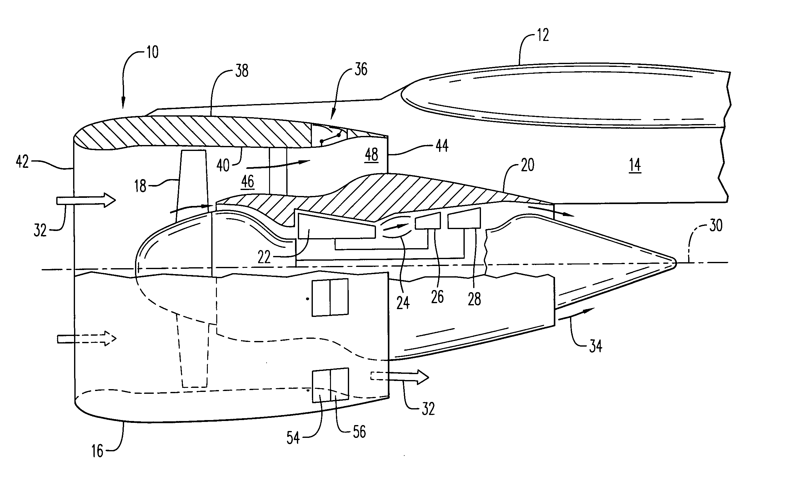
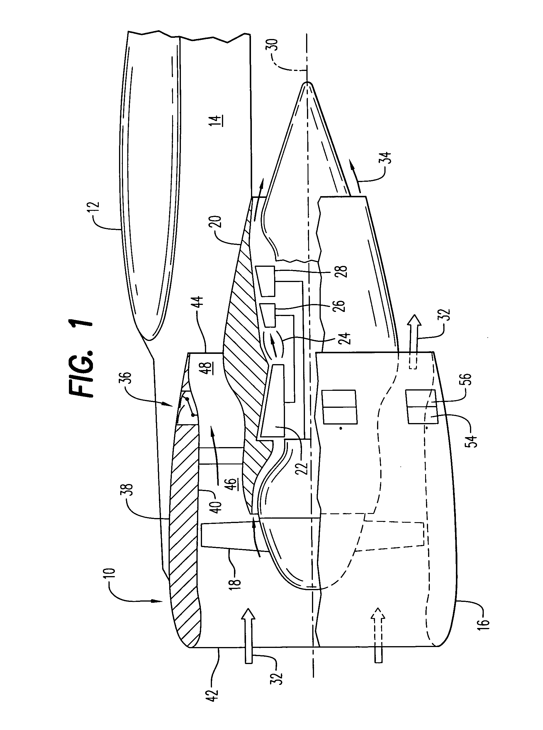
[0022] Illustrated in FIG. 1 is a turbofan aircraft gas turbine engine 10 suitably mounted to the wing 12 of an aircraft by a supporting pylon 14. Alternatively, the engine could be mounted to the fuselage of the aircraft if desired.

[0023] The engine includes an annular fan nacelle 16 surrounding a fan 18 which is powered by a core engine surrounded by a core nacelle or cowl 20. The core engine includes in serial flow communication a multistage axial compressor 22, an annular combustor 24, a high pressure turbine 26, and a low pressure turbine 28 which are axisymmetrical about a longitudinal or axial centerline axis 30.

[0024] During operation, ambient air 32 enters the fan nacelle and flows past the fan blades into the compressor 22 for pressurization. The compressed air is mixed with fuel in the combustor 24 for generating hot combustion gases 34 which are discharged through the high and low pressure turbine 26,28 in turn. The turbines extract energy from the combustion gases and...


PUM


Abstract

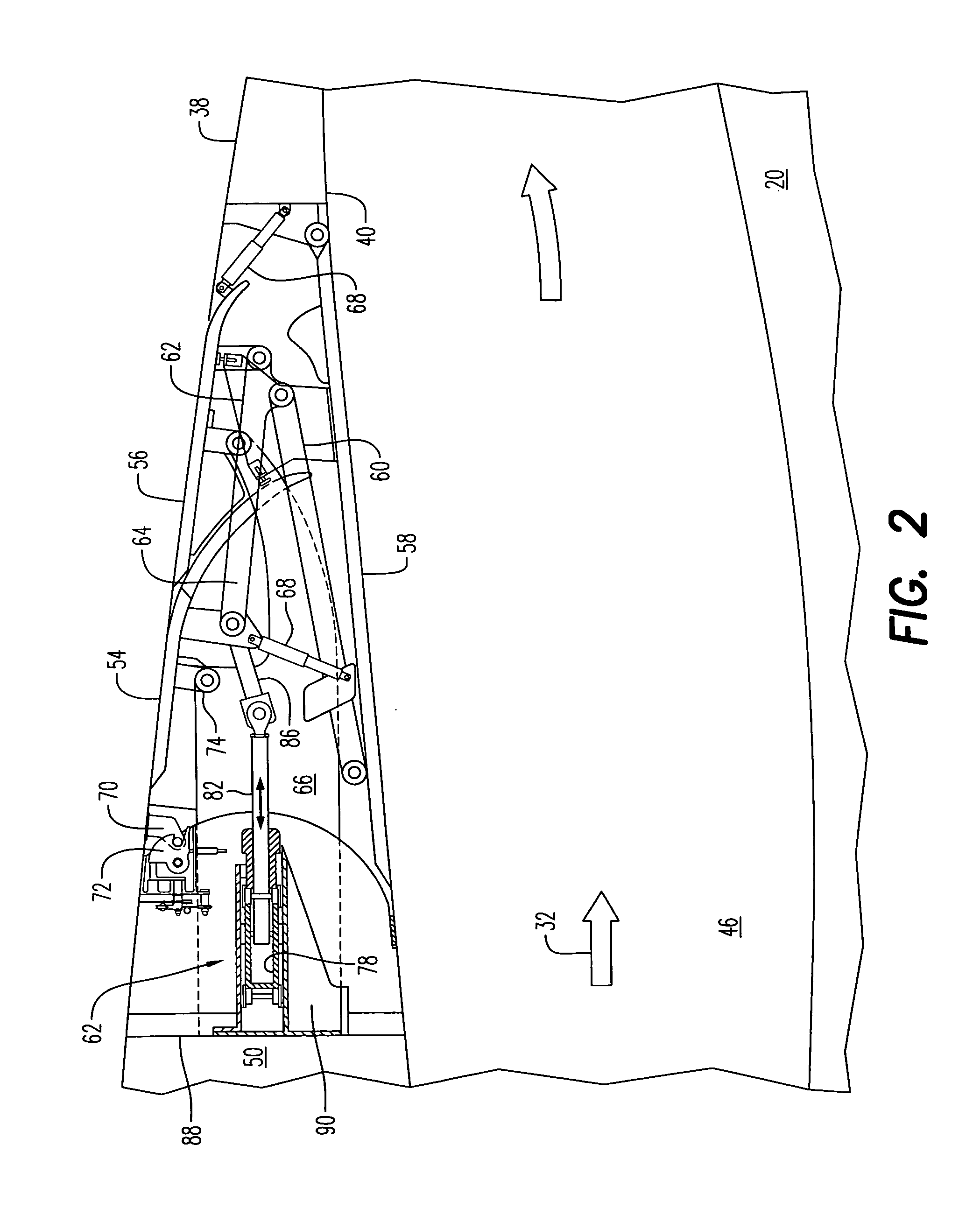
A thrust reverser includes reverser doors circumferentially spaced around a nacelle. An arcuate yoke is disposed coaxially around the nacelle. An actuator is mounted tangentially to the yoke for rotary movement thereof. Actuator rods join the doors to the yoke for simultaneous deployment of the doors as the yoke is rotated.

Description

[0001] This application claims the benefit of U.S. Provisional Application 60 / 508,504; filed Oct. 2, 2003.BACKGROUND OF THE INVENTION [0002] The present invention relates generally to aircraft engines, and, more specifically, to thrust reversers therein. [0003] A typical turbofan aircraft engine includes a fan powered by a core engine for producing propulsion thrust for powering the aircraft in flight. The core engine typically has in serial flow communication a multistage axial compressor, annular combustor, and high pressure turbine joined to the compressor by one shaft. A second shaft joins the fan to a low pressure turbine disposed downstream from the high pressure turbine. [0004] The engine also includes a fan nacelle surrounding the cowling or nacelle of the core engine which defines an annular bypass duct therebetween. The nacelle may be short and terminates in a fan outlet nozzle surrounding the core engine upstream from an independent core exhaust nozzle at the downstream e...

Claims


Application Information

Patent Timeline
IPC IPC(8): F02K1/70F02K1/72F02K1/76
CPCF02K1/70Y02T50/671F02K1/763F02K1/72Y02T50/60
Inventor LAIR, JEAN-PIERRE
Owner AERONAUTICAL CONCEPT OF EXHAUST
Learn More