
Connection device, connector unit, connectors, and electronic equipment

a technology of connecting devices and electronic equipment, which is applied in the direction of coupling device connections, incorrect coupling prevention, electrical equipment, etc., can solve the problems of complicated structure, difficult connection of adapters and hard drives, and possible difficulties in connecting adapters and the first electronic equipment, so as to reduce the number of components and simplify the structure. , the effect of easy adjustmen

Inactive Publication Date: 2005-07-07
SONY COMPUTER ENTERTAINMENT INC +1
View PDF4 Cites 7 Cited by
  • Summary
  • Abstract
  • Description
  • Claims
  • Application Information

AI Technical Summary

Benefits of technology

[0009] With this configuration of the present invention, at least one of the socket or the engaging member of the connector attached to the base member is provided with a loose-fit portion that is inserted into the hole of the base member and has the diameter smaller than the diameter of the hole and the length along the insertion direction greater than the thickness of the base member, and thus the attachment position of the connector can be arbitrarily adjusted to the base member.
[0041] Since electronic equipment of the present invention has the above-described connector unit, the attachment position of the connector can be easily adjusted, and reduction of the number of components and simplification of the structure can be achieved.

Problems solved by technology

When these connectors are completely fixed, connection of the adapter and the hard disk and connection of the adapter and the first electronic equipment possibly become difficult due to transition of the attachment position.
However, such a conventional adapter has a problem in which it requires many components like the base member 84 and the movable plate 82, as well as its complicated structure.

Method used


Image

  • Connection device, connector unit, connectors, and electronic equipment
  • Connection device, connector unit, connectors, and electronic equipment
  • Connection device, connector unit, connectors, and electronic equipment

Examples


Embodiment Construction

[0054] An embodiment of the present invention will be described below with reference to the attached drawings.

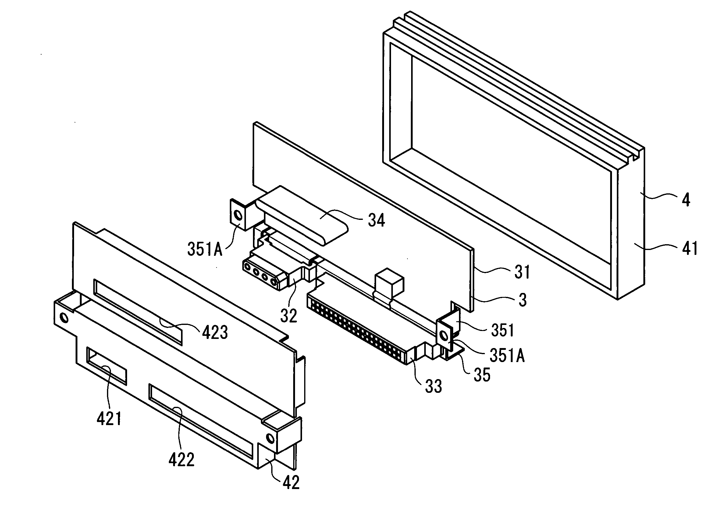
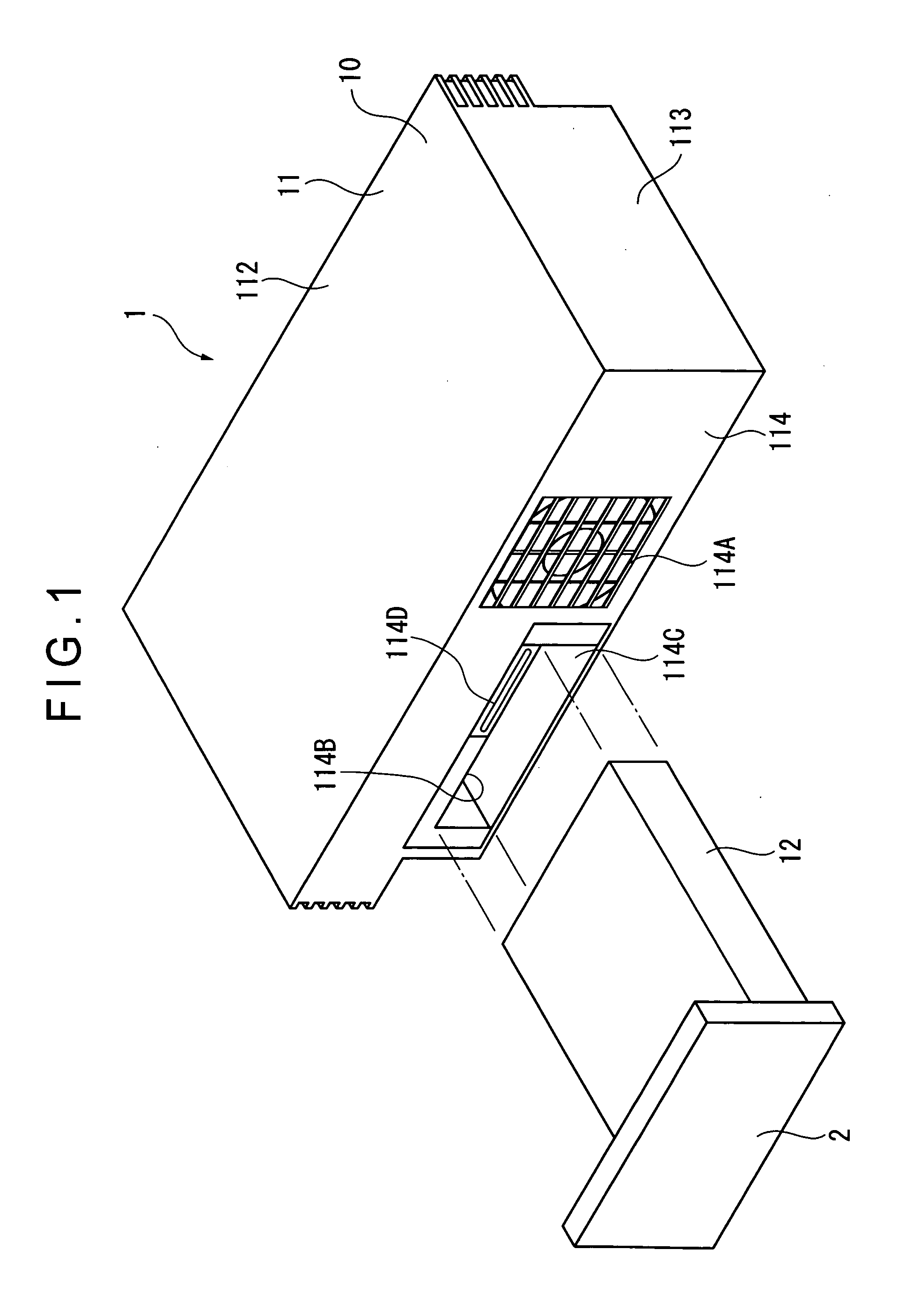
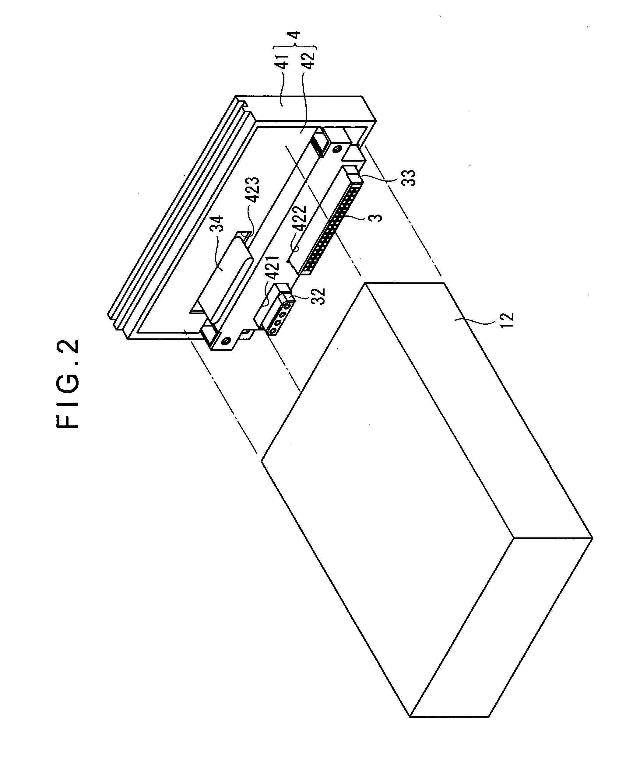
[0055]FIG. 1 shows an entertainment device 1 as an electronic equipment. The entertainment device 1 has functions for reading out a game program recoded in an optical disc etc. to execute the game according to a direction of a user and reproducing image, music, and the like recorded in an optical disc. The entertainment device 1 has a first electronic equipment 10 including a disc device, CPU (Central Processing Unit), a controller slot, a memory slot, and a master electrical switch etc., which are not shown; a HDD 12 as a second electronic equipment (another electronic equipment); and an adapter (connecting device) 2 mutually connecting the HDD 12 and the first electronic equipment 10.

[0056] The first electronic equipment 10 has a casing 11. The casing 11 is formed to be a rectangular shape in plan view and a substantially L-shape in a cross section, and is provided with ...


PUM


Abstract

A socket (333) of a connector (33) of an adapter (2) has a projecting portion (loose-fit portion) (333B) inserted into a hole (353A) of a base member (35) to support the connector (33) in loosely fitted manner. A diameter (L3) of the projecting portion (333B) is smaller than a diameter L4 of a hole (353A) of the base member (35). A length (L5) along an insertion direction into the hole (353A) is greater than a thickness of the connector attachment side (353). The connector (32) of the adapter (2) has an insertion portion (323) inserted into a cutout portion (353B) of the base member (35). A length (L8) of an extending direction of an insertion body (323A) of the insertion portion (323) is greater than the thickness (L9) of the connector attachment side, while its width (L6) is smaller than a width (L7) of the cutout portion (353B).

Description

TECHNICAL FIELD [0001] The present invention relates to a connecting device, a connector unit, a connector, and an electronic equipment. BACKGROUND ART [0002] Conventionally, an entertainment device having a first electronic equipment as an entertainment device body, a second electronic instrument connected to the first electronic equipment, and, HDD (Hard Disk Drive) etc., for example, for enhancing storage capacity of the first electronic equipment has been used. In many cases, the hard disk and the first electronic instrument are connected through an adapter (connecting device). [0003] The adapter is provided with a plurality of connectors such as a power source connector, an IDE (Integrated Device Electronics) connector, a connector connected to the first electronic equipment, and the like. When these connectors are completely fixed, connection of the adapter and the hard disk and connection of the adapter and the first electronic equipment possibly become difficult due to trans...

Claims


Application Information

Patent Timeline
IPC IPC(8): H01R13/518H01R13/631H01R13/74
CPCH01R13/518H01R13/6315H01R13/748H01R13/743H01R13/74
Inventor OOTORI, YASUHIRONAGASE, KENICHITOKUSASHI, MITSUYUKIHASEGAWA, TOMONORIYAGI, HIRONORI
Owner SONY COMPUTER ENTERTAINMENT INC
Learn More