
System and method for positioning projectors in space to steer projections and afford interaction

a projection system and projector technology, applied in the field of positioning systems for interactive display devices, can solve the problems of occlusion of line of sight of projectors, system not equipped for interaction, limited physical space that can be effectively projected upon,

Inactive Publication Date: 2005-06-16
IBM CORP
View PDF8 Cites 95 Cited by
  • Summary
  • Abstract
  • Description
  • Claims
  • Application Information

AI Technical Summary

Problems solved by technology

Although this system is designed for projecting an image onto a surface in a room, this system is not equipped for interaction.
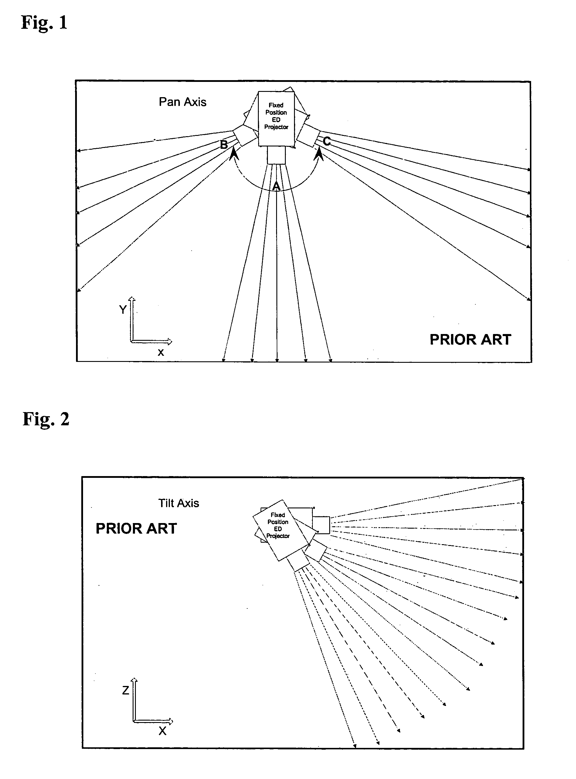
Since the projection and vision system bases are fixed, the physical space that can be effectively projected upon is limited by the position and capabilities of hardware included in the system.
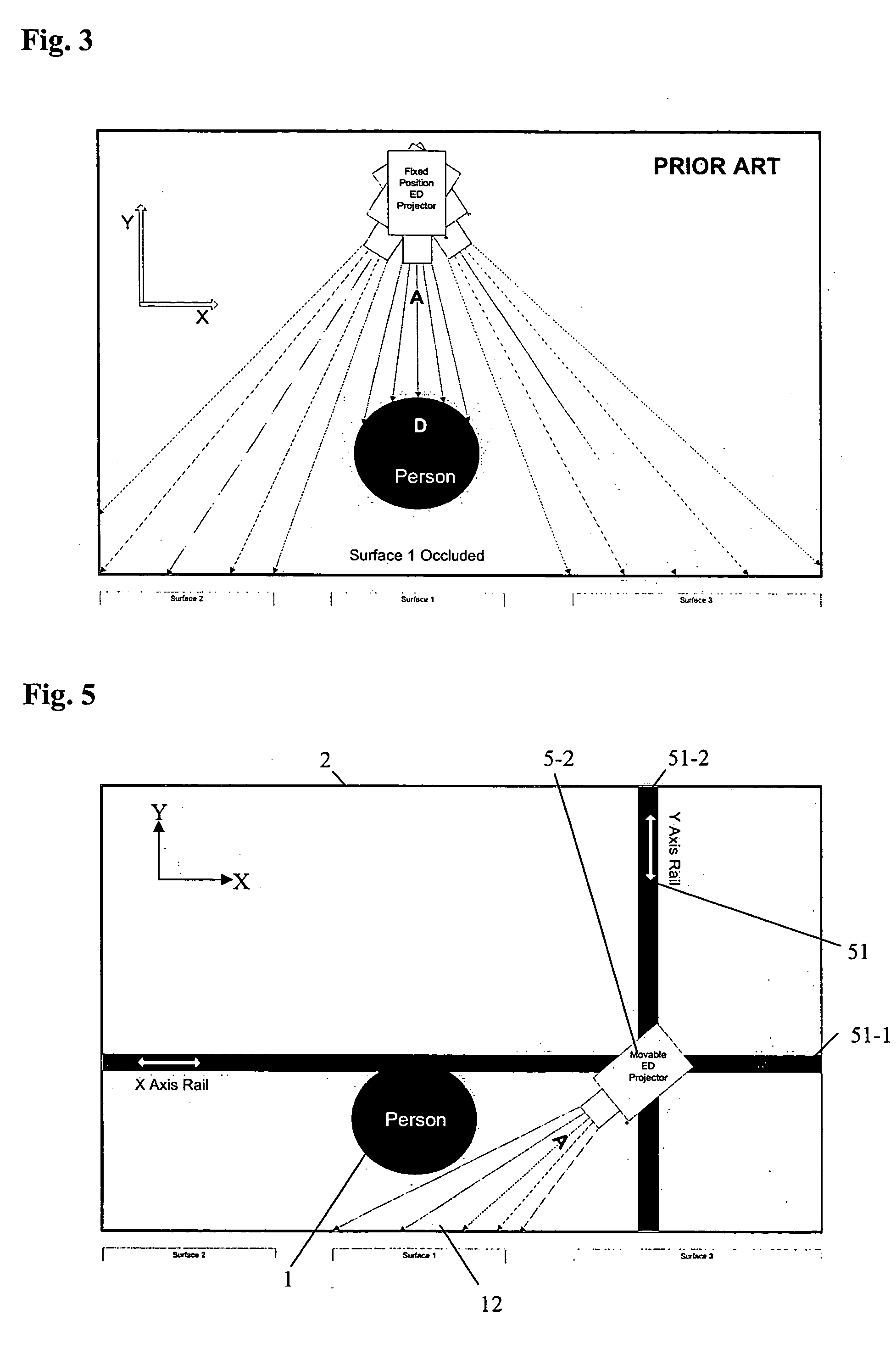
One problem that is inherent in the “line of sightprojector is occlusion.
This type of problem is depicted in FIG. 3 (prior art), where a portion of surface 1 is occluded by a person D. Due to the fixed base of this mounting system, the projector is generally limited in the surfaces that can be reached.
However, such implementations can be excessively expensive.
For example, many projectors may be required while some portions of the setting may experience limited use.
For example, as present projectors serve only one request a time, fixed equipment used in high traffic areas may become bottlenecked with traffic, and cause user wait time.
This may be detrimental to user acceptance of the technology by frustrating users who wait in line and stand witness to nearby equipment sitting idle.
However, due to limitations in existing designs for mounting systems, such systems may have limited availability, and be unnecessarily expensive.
The variety of applications for present systems is therefore limited by the present mounting systems.

Method used


Image

  • System and method for positioning projectors in space to steer projections and afford interaction
  • System and method for positioning projectors in space to steer projections and afford interaction
  • System and method for positioning projectors in space to steer projections and afford interaction

Examples


Embodiment Construction

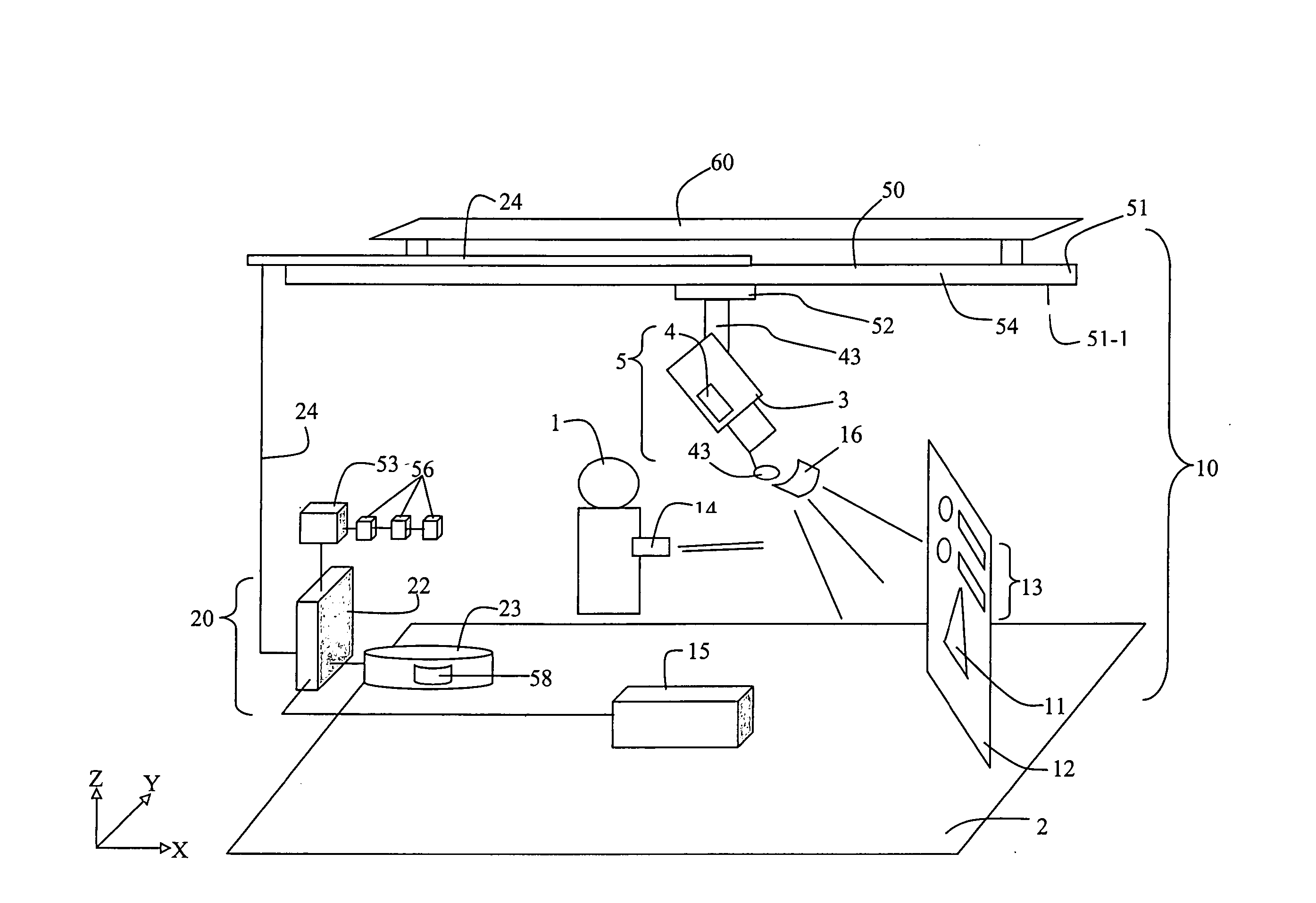
[0032] Disclosed herein are methods and apparatus for positioning and controlling a projection unit. The projection unit is suited for use in retail outlets, manufacturing environments, office environments, planning meetings, and other settings. Typically, the projection unit provides for display of images on surfaces that are a part of the setting (e.g., a wall). The projection unit may include an interactive component for user input. Aspects of the projection unit are described in U.S. Pat. No. 6,431,711, entitled “Multiple-Surface Display Projector with Interactive Input Capability,” issued to Pinhanez on Aug. 13, 2002. The disclosure of U.S. Pat. No. 6,431,711 is incorporated by reference herein in its entirety.

[0033] The projection system discussed herein generally includes a positioning system for providing a variety of positions and orientations for a projection unit. The projection unit is mounted on the positioning system, typically by use of a mount. In one embodiment, bo...


PUM


Abstract

A positioning system for locating at least one interactive projection unit, and methods for operation thereof is disclosed. The positioning system includes equipment for providing multiple degrees of freedom for locating the at least one projection unit. The at least one projection unit is equipped with various components and capabilities to provide for projection onto surfaces within a variety of settings, and thus provide for display, information, interaction and computing in the variety of settings.

Description

TECHNICAL FIELD OF THE INVENTION [0001] This invention relates to positioning systems for interactive display devices useful in retail, manufacturing, and other such settings. BACKGROUND OF THE INVENTION [0002] A concept having growing popularity is that of ubiquitous computing. Certain technologies have been developed, or are presently in development, to further provide for ubiquitous computing. Some examples of such systems are presented in the publication by Claudio Pinhanez, entitled “The Everywhere Displays Projector: A Device to Create Ubiquitous Graphical Interfaces,” appearing in the Proceedings of Ubiquitous Computing 2001 (Ubicomp”01), Atlanta, Ga., September 2001; a publication by Gopal Pingali, Claudio Pinhanez, Anthony Levas, Rick Kjeldsen, Mark Podlaseck, Han Chen, Noi Sukaviriya, Mark Weiser, entitled “Steerable Interfaces for Pervasive Computing Spaces,” appearing in the proceedings of the IEEE International Conference on Pervasive Computing and Communications—PerCom...

Claims


Application Information

Patent Timeline
Patent Type & Authority Applications(United States)
IPC IPC(8): G03B21/14
CPCG03B21/14H04N9/3185H04N9/3194G03B21/145
Inventor PINGALI, GOPALPINHANEZ, CLAUDIOPODLASECK, MARK EDWARDLEVAS, ANTHONYKJELDSEN, FREDERIK C.M.
Owner IBM CORP
Learn More