
Object operation apparatus, object operation method and object operation program

Inactive Publication Date: 2005-03-17
DAINIPPON SCREEN MTG CO LTD
View PDF3 Cites 127 Cited by
  • Summary
  • Abstract
  • Description
  • Claims
  • Application Information

AI Technical Summary

Benefits of technology

[0017] An operator is not required to repeat the digital operation for each of the plurality of second objects. This can reduce burdens in operating objects imposed on the operator.
[0019] An operator is not required to repeat the digital operation for each of the plurality of second objects. This can reduce burdens in operating objects imposed on the operator.
[0021] An operator is not required to specify a plurality of objects that correspond to the second object or perform an object operation repeatedly. This can reduce burdens in operating objects imposed on the operator.
[0022] It is therefore an object of the present invention to improve the efficiency in operating objects displayed on the display.

Problems solved by technology

In the conventional drag and drop operation, however, a plurality of icons can be dragged, but those icons can only be dropped on one icon.
This causes a problem in that, for operating a plurality of files, the drag and drop operation using a pointing device needs to be performed repeatedly.
However, the conventional technique does not sufficiently solve the problem in that an operation using a pointing device needs to be performed repeatedly.
That is, with the conventional technique, a plurality of icons (objects) cannot be selected by one drag, or one or more files cannot be copied or moved to a plurality of directories only by one drag and drop operation.
Accordingly, an operator needs to perform the drag and drop operation several times in order to copy or move one or more files to a plurality of directories, which imposes operational burdens on the operator.

Method used


Image

  • Object operation apparatus, object operation method and object operation program
  • Object operation apparatus, object operation method and object operation program
  • Object operation apparatus, object operation method and object operation program

Examples


first preferred embodiment

1-1. Configuration of Object Operation Apparatus

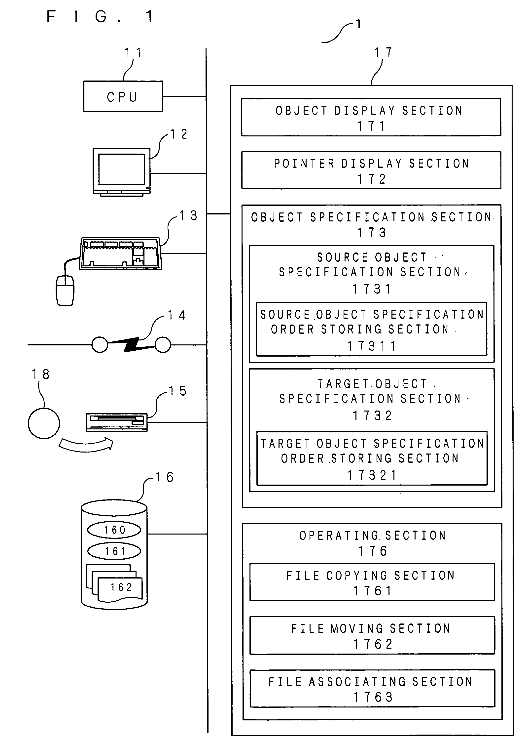
[0042]FIG. 1 shows the configuration of an object operation apparatus 1 according to the present invention. The object operation apparatus 1 is a computer system configured by a general-purpose personal computer, including a CPU11, a display 12, an input device 13, a network I / F (interface) 14, a media drive 15, a storage 16 and a memory 17.

[0043] The CPU11 executes an operation in accordance with an OS 160 stored in the storage 16, for controlling operational conditions of hardware and software implemented in the computer. Further, the CPU11 executes a program 161 recorded in a media disk 18 inserted into the media drive 15, at the memory 17, for performing the functions of the object operation apparatus 1.

[0044] The display 12 is used to display information necessary for an object operation. That is, the display 12 displays objects such as icons, a pointer for pointing to objects, and the like.

[0045] The input device 13 includes ...

second preferred embodiment

[0150] Next, a second preferred embodiment of the present invention will be discussed. The object operation apparatus 1 according to this embodiment is the same as in the first preferred embodiment except the process of object operation. The following discussion will be focused on this difference.

2.1. Process of Object Operation

[0151]FIG. 6 is a flowchart showing a process of an object operation performed between files or folders represented by a plurality of source objects and files or folders represented by a plurality of target objects in one-to-one correspondence with each other.

[0152] Step S101 is similar to step S1 shown in FIG. 2 and step S11 shown in FIG. 3, in which objects are displayed on the display 12 prior to an object operation.

[0153] In step S102, the specification order storing section 17311 provided in the source object specification section 1731 and the specification order storing section 17321 provided in the target object specification section 1732 are both ...

third preferred embodiment

[0173] Next, a third preferred embodiment of the present invention will be discussed. The object operation apparatus 1 according to this embodiment is the same as that of the first preferred embodiment except that it includes a target object attribute retrieving section 174 and a target file attribute assigning section 175, and except the process of object operation. The following discussion will be focused on these differences.

[0174] Similar components as in the object operation apparatus 1 according to the first preferred embodiment are indicated by the same reference characters. These components have already been discussed in the first preferred embodiment, and explanation thereof is omitted here.

3.1. Configuration of Object Operation Apparatus

[0175]FIG. 10 shows the configuration of the object operation apparatus 1 according to the present invention. The attribute retrieving section 174 searches attributes of target objects specified by the target object specification section...


PUM


Abstract

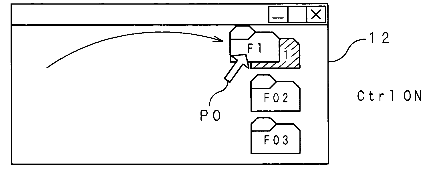
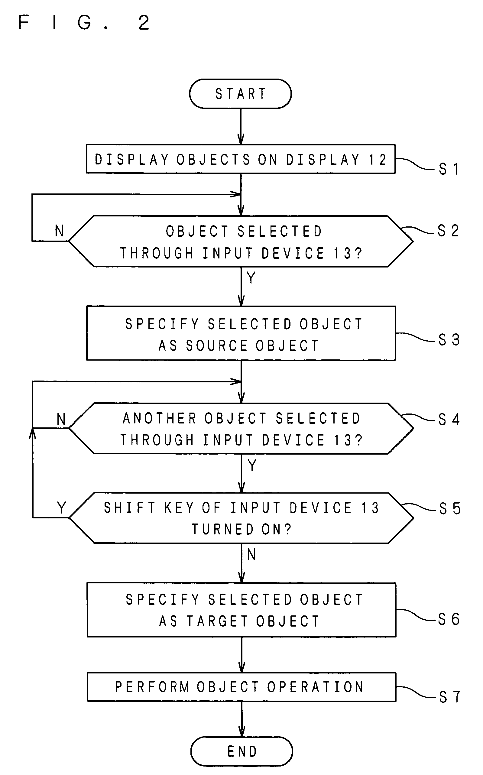
A first icon displayed on a display is selected, and is specified by a source object specification section as a source object. Next, the first icon is dragged to the vicinity of a second icon (folder), so that the second icon is selected. Then, the first icon is dragged to the vicinity of third and fourth icons (folders) with a “Shift” key on a keyboard of an input device pressed, so that the third and fourth icons are selected. Next, the selected second to fourth icons are specified as target objects. The source object (file) is then copied to each of the target objects (folders).

Description

BACKGROUND OF THE INVENTION [0001] 1. Field of the Invention [0002] The present invention relates to an object operation apparatus, an object operation method and an object operation program for displaying, on a display, files or folders for use in a computer in the form of objects in one-to-one correspondence with the files or folders, and carrying out a predetermined operation on the objects. [0003] 2. Description of the Background Art [0004] In an operating system (OS) for use in a personal computer (hereinafter briefly referred to as a “computer”) such as Windows XP (a trademark of Microsoft Corp.) and Mac OS (a trademark of Apple Computer, Inc.), a graphical user interface (GUI) has been put into practice in which an object such as an icon representing a file, folder or the like is displayed on a display screen, and the icon is operated so that the file, folder or the like represented by the icon is copied or moved, for example. [0005] That is, the OS can display a data file, a...

Claims


Application Information

Patent Timeline
IPC IPC(8): G06F3/033G06F3/048
CPCG06F3/0486
Inventor FUKASE, MASAYUKIYAMASHITA, TOMOKO
Owner DAINIPPON SCREEN MTG CO LTD
Learn More