Boat lift

a technology for lifting boats and boats, applied in the field of boat lifts, can solve the problems of requiring a large amount of space, requiring unsightly overhead steel construction, and difficult access to such components, and achieving the effect of improving the safety of passengers and crew, reducing the risk of accidents, and improving safety

Inactive Publication Date: 2005-03-17
WAY MARINE DESIGN INC
View PDF39 Cites 16 Cited by
  • Summary
  • Abstract
  • Description
  • Claims
  • Application Information

AI Technical Summary

Benefits of technology

[0028]FIG. 15 is an enlarged front elevational view of the fluid reservoir shown in FIG. 11 including remote control apparatus.

Problems solved by technology

However, conventional hydraulic boat lifts employing such pulleys and cables typically require unsightly overhead steel construction and are free standing, i.e. not secured to a dock, as illustrated in FIG. 1 of published U.S. Patent Application No. 2002 / 0150427 and U.S. Patent No. Re. 32,118 both to Godbersen, for example.
As a result, such boat lifts must be supported by four pilings and require a large amount of space for allowing a boat to maneuver therebetween.
In addition, such boatlifts typically position their mechanical / electrical components at heights well-above an operator's reach thereby making access to such components difficult.

Method used


Image

  • Boat lift
  • Boat lift
  • Boat lift

Examples


Embodiment Construction

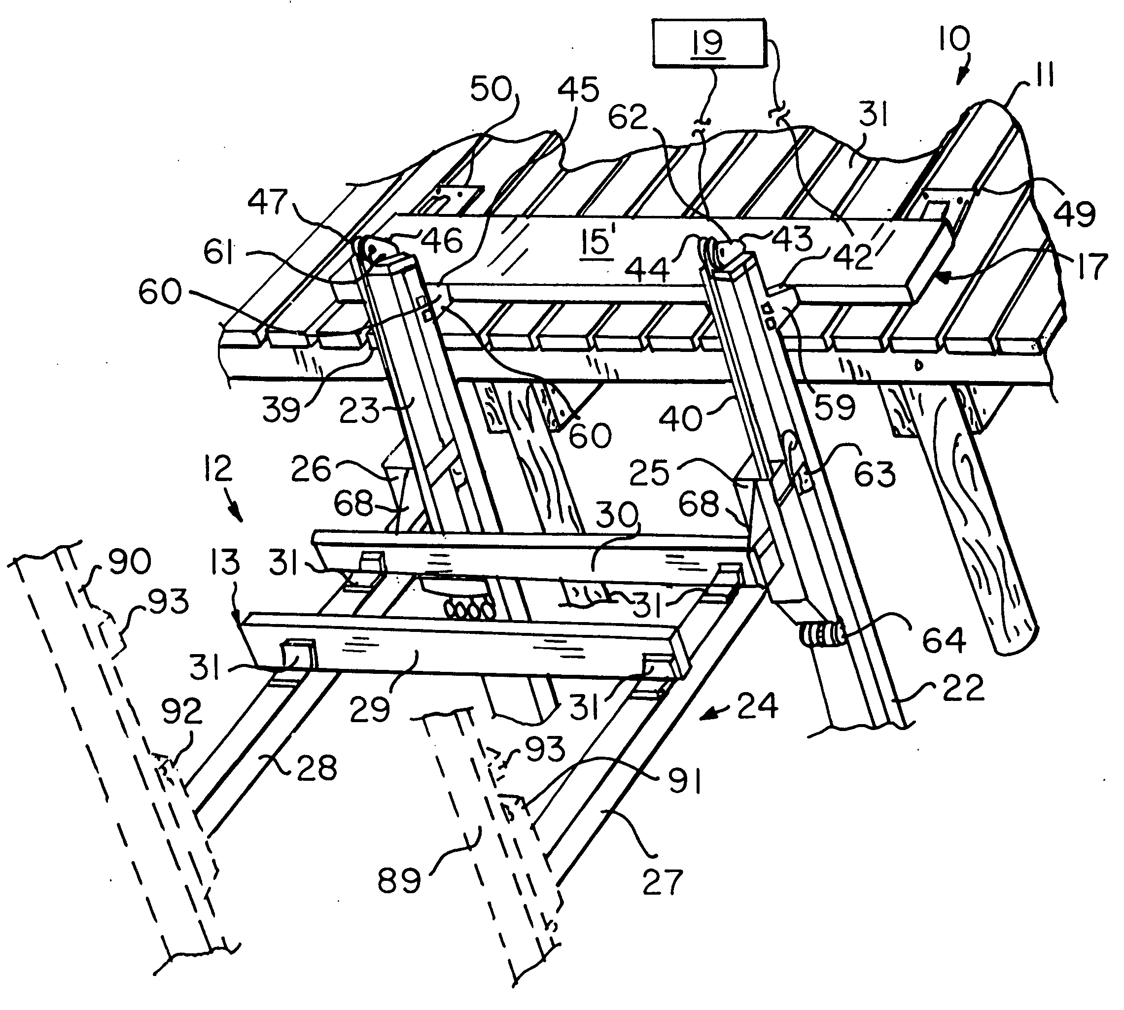
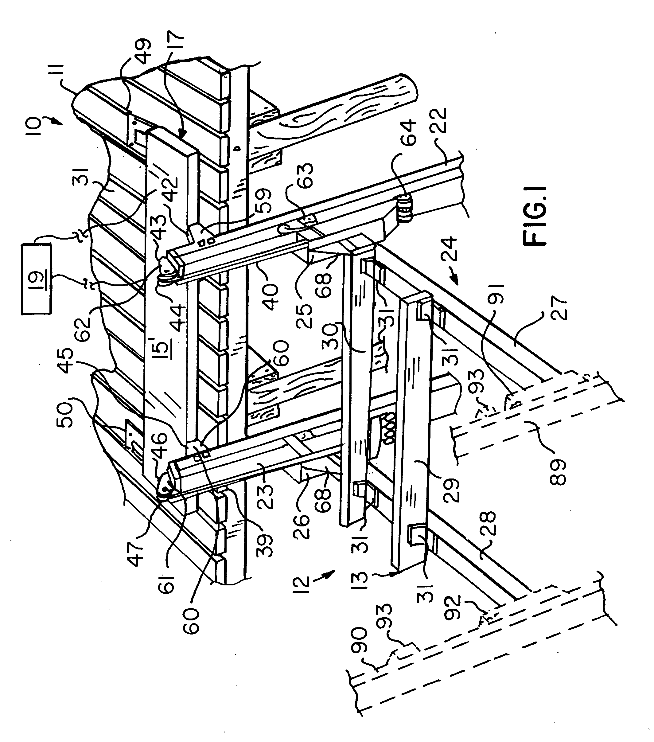
[0029] The present invention will now be described more fully hereinafter with reference to the accompanying drawings, in which preferred embodiments of the invention are shown. This invention may, however, be embodied in many different forms and should not be construed as limited to the embodiments set forth herein. Rather, these embodiments are provided so that this application will be thorough and complete, and will fully convey the true scope of the invention to those skilled in the art. Like numbers refer to like elements throughout, and prime and double prime notations are used to indicate similar elements in alternate embodiments.

[0030] The present invention is a hydraulically operated boat lift shown generally at numeral 12 securable to the end of a dock 11, as generally shown at 10 in FIG. 1. The boat lift 12 is also securable to a bulkhead (not shown) or other similar structure that can sufficiently support the combined weight of a boat and boat lift 12.

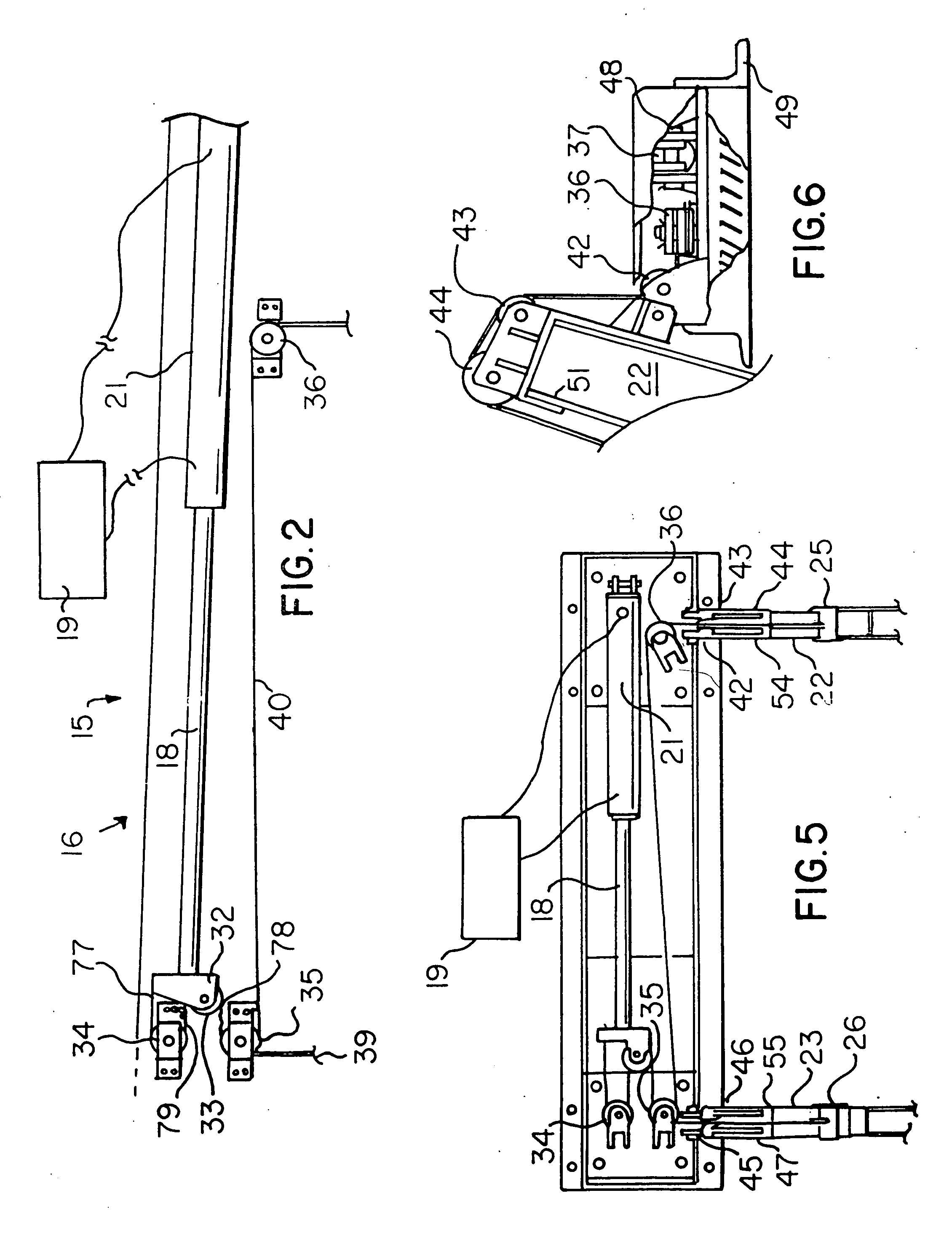
[0031] In constru...


PUM


Abstract

An assembly for lifting a boat locatable adjacent a dock requires only two elongate vertically disposed pilings each having a lower end portion mounted into the floor of a body of water near the dock and an upper end portion extending upwardly adjacent the dock. A lift is connected to a boat cradle for moving the cradle substantially vertically and includes a piston/cylinder attached between the dock and cables, which are mounted to each piling and are connected between the piston and the cradle. The piston is movable between a first position for lifting and pulleys and guides are mounted to the pilings and the cradle.

Description

CROSS REFERENCE TO RELATED APPLICATIONS [0001] Not Applicable. STATEMENT REGARDING FEDERALLY SPONSORED RESEARCH OR DEVELOPMENT [0002] Not Applicable. REFERENCE TO A MICROFICHE APPENDIX [0003] Not Applicable. BACKGROUND OF THE INVENTION [0004] 1. Field of the Invention [0005] This invention relates to a boat lift and, more particularly, to a hydraulically operated boat lift including a plurality of pulleys for raising and lowering a boat along two pilings. [0006] 2. Related Art [0007] A multiplicity of boat lifts have been employed by prior art for docking vessels or lifting them out of the water for servicing. One type of such boatlifts is hydraulically operated by a plurality of pulleys and cables. However, conventional hydraulic boat lifts employing such pulleys and cables typically require unsightly overhead steel construction and are free standing, i.e. not secured to a dock, as illustrated in FIG. 1 of published U.S. Patent Application No. 2002 / 0150427 and U.S. Patent No. Re. 3...

Claims


Application Information

Patent Timeline
Patent Type & Authority Applications(United States)
IPC IPC(8): B63C3/06B63C3/12
CPCB63C3/12B63C3/06
Inventor WAY, ROBERT L.
Owner WAY MARINE DESIGN INC
Why Eureka
Try Eureka