


Quick Research
Generate reliable direction feasibility study reports for your R&D in just a few steps.

Technical Q&A
Discover and master advanced knowledge NOW. Basics, ideas, possibilities, all at once.

Find Solutions
As an expert in R&D theories, this can generate solutions to your technical problems instantly.

Evaluate Feasibility
Analyze your overall solution with one click, know your potential R&D risks in advance.

Monitor Landscape
Get weekly tech updates, stay abreast of the latest tech innovations and key insights.
Apparatus and method for automatically unloading brick from kiln cars and preparation for shipment
- Summary
- Abstract
- Description
- Claims
- Application Information
AI Technical Summary
Benefits of technology
Problems solved by technology
Method used
Image

Examples
first embodiment
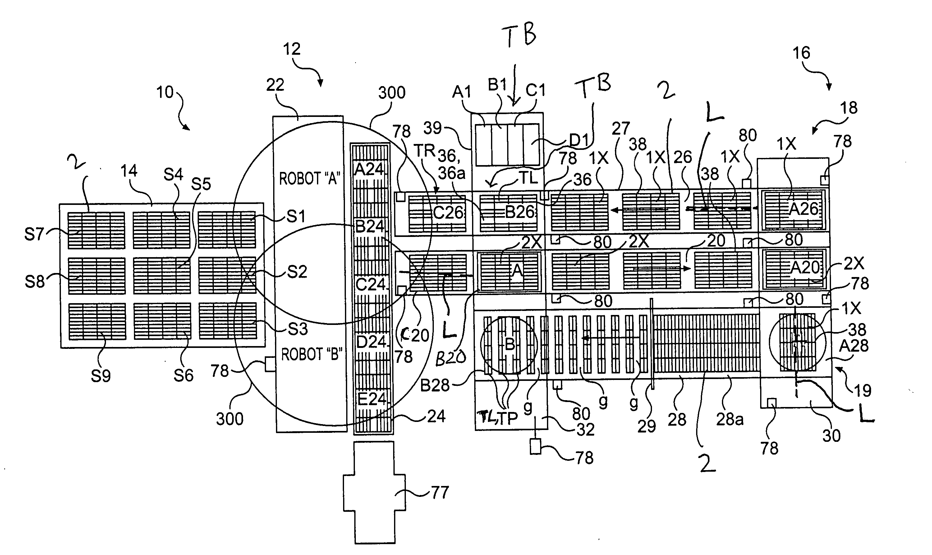
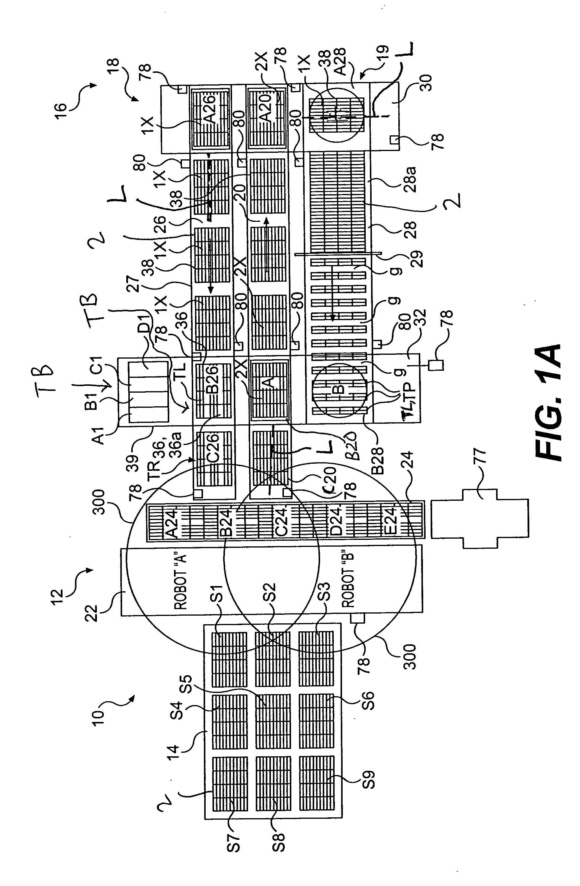
[0054] Further, because of the rectangular shape of the bricks and subsequently of the one-layer or two-layer stacks of bricks, or other number of layer(s) stack(s) of brick (nX), the layers that are transferred onto the conveyors may be oriented such that their longitudinal axes L are either parallel or perpendicular to the direction of travel of the conveyors 20,26,28, with the direction of travel of the conveyors 20,26,28 being indicated by the arrows on the conveyors 20,26,28 in FIGS. 1A, 1B and 1C. For example, in the first embodiment as illustrated in FIG. 1A, the two-layer stacks 2X, or other number of layer(s) stack(s) of brick (nX), are transferred onto the infeed conveyor 20 parallel to the infeed conveyor's direction of travel, and the layers 1X, or other number of layer(s) stack(s) of brick (nX), are transferred onto the outfeed conveyor 26 parallel to outfeed conveyor's direction of travel, while the layers 1X, or other number of layer(s) stack(s) of brick (nX), transfe...
second embodiment
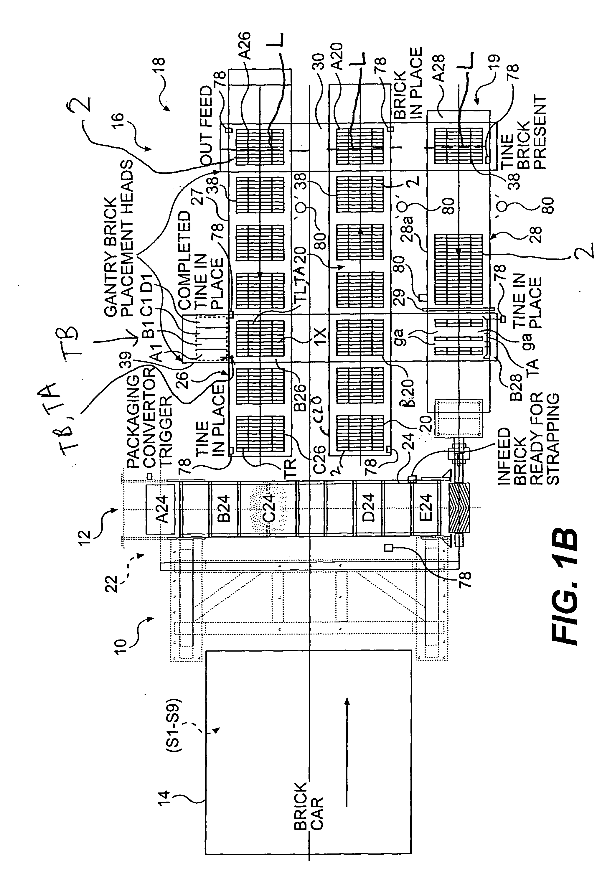
[0062] In FIG. 1B, the distribution carriage 31 will not rotate the clamped brick layer being transferred to the outfeed conveyor 26 as the layers intended for the outfeed conveyor 26 in this embodiment are supposed to be positioned perpendicular to the outfeed conveyor's direction of travel. The distribution carriage 31 likewise will not rotate the clamped brick layer being transferred to the tine conveyor 28 by 90° since those layers are supposed to be positioned perpendicular to the outfeed conveyor's direction of travel.
third embodiment
[0063] Conversely, in FIG. 1C, the distribution carriage 31 will rotate the clamped brick layer being transferred to the outfeed conveyor 26 by 90° as the layers intended for the outfeed conveyor 26 are supposed to be positioned parallel to the outfeed conveyor's direction of travel. The distribution carriage 31 will not, on the other hand, rotate the clamped brick layer being transferred to the tine conveyor 28 by 90° since those layers are supposed to be positioned perpendicular to the outfeed conveyor's direction of travel.
[0064] Outfeed conveyor 26 progressively moves the brick layer 1X, or other number of layer(s) stack(s) of brick (nX), (i.e., by indexing) placed by the distribution carriage 31 so as to position the brick layer beneath the tine carriage structure 32 elevated above the outfeed conveyor 26. The movement of the outfeed conveyor 26 thus opens a clear space in position A26 for receiving the next single brick layer 1X, or other number of layer(s) stack(s) of brick (...
PUM
 Abstract
Description
Claims
Application Information
 - R&D Engineer
- R&D Manager
- IP Professional
- Industry Leading Data Capabilities
- Powerful AI technology
- Patent DNA Extraction
Browse by: Latest US Patents, China's latest patents, Technical Efficacy Thesaurus, Application Domain, Technology Topic, Popular Technical Reports.
© 2024 PatSnap. All rights reserved.Legal|Privacy policy|Modern Slavery Act Transparency Statement|Sitemap|About US| Contact US: help@patsnap.com