
Overlay binder

Inactive Publication Date: 2005-03-10
AVERY DENNISON CORP
View PDF29 Cites 15 Cited by
  • Summary
  • Abstract
  • Description
  • Claims
  • Application Information

AI Technical Summary

Problems solved by technology

However, such arrangements may be somewhat unfinished or unprofessional in their appearance.

Method used


Image

  • Overlay binder
  • Overlay binder
  • Overlay binder

Examples


Embodiment Construction

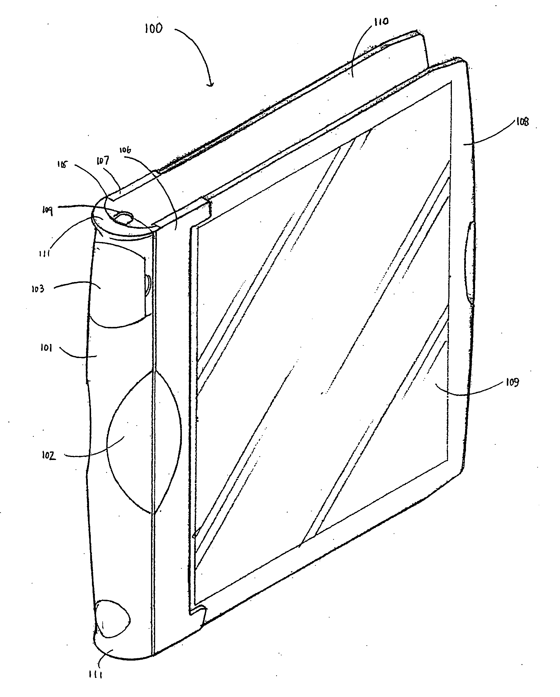
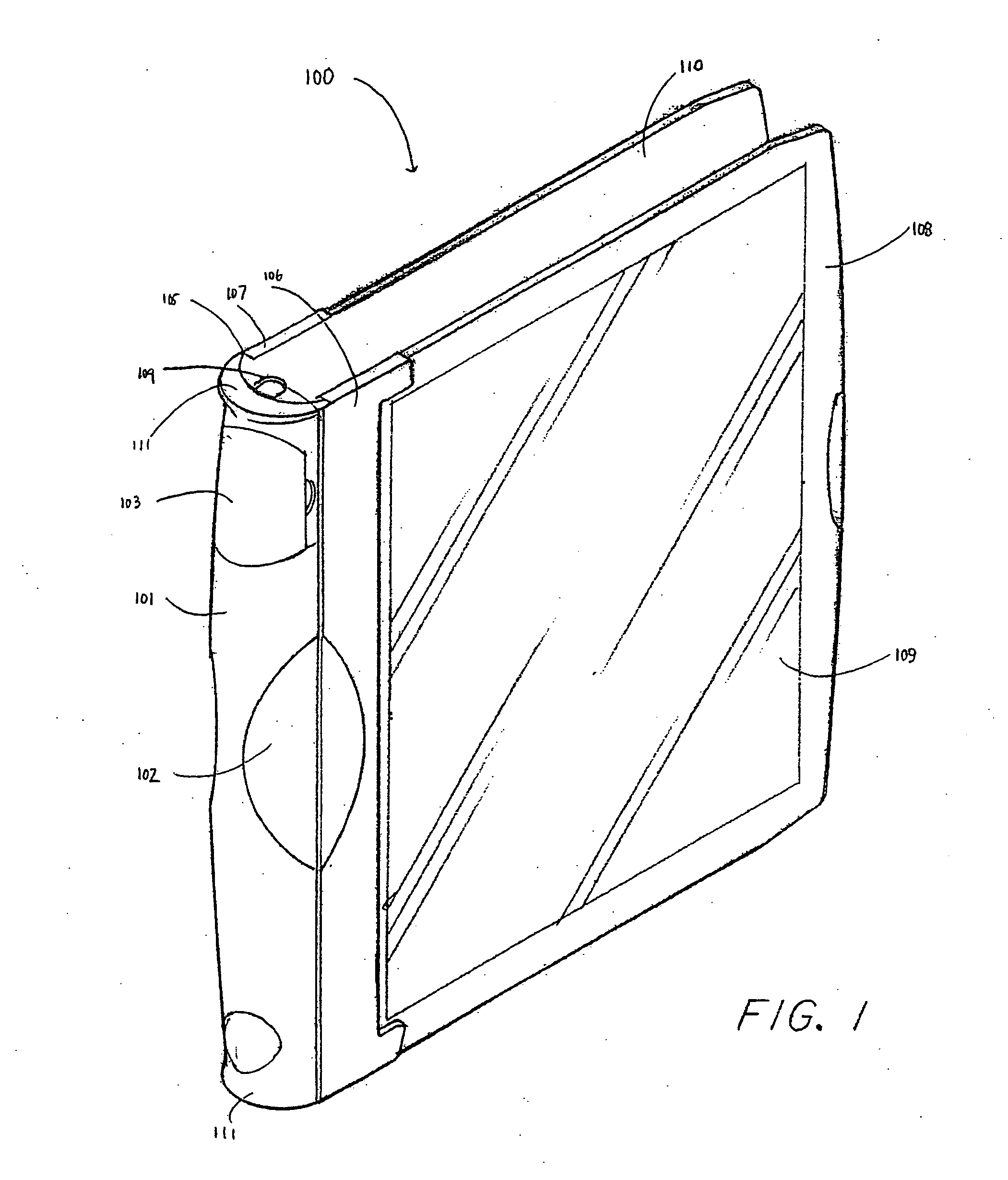
[0015] As shown in FIG. 1, an exemplary binder 100 is composed of a front cover 108 and a back cover 110 joined to a spine 101. The front cover 108 is a generally planar surface made from polypropylene having a substantially transparent window 109. As shown in FIG. 1, the window 109 is unitary with the front cover 108. More specifically, the window 109 is a polished portion of the front cover 108. Because the window 109 is unitary with the front cover 108, the front cover is substantially rigid structure. Furthermore, the perimeter surrounding the window 109 may be textured to create the appearance of a frame so as to improve the aesthetic appearance of the front cover 108.

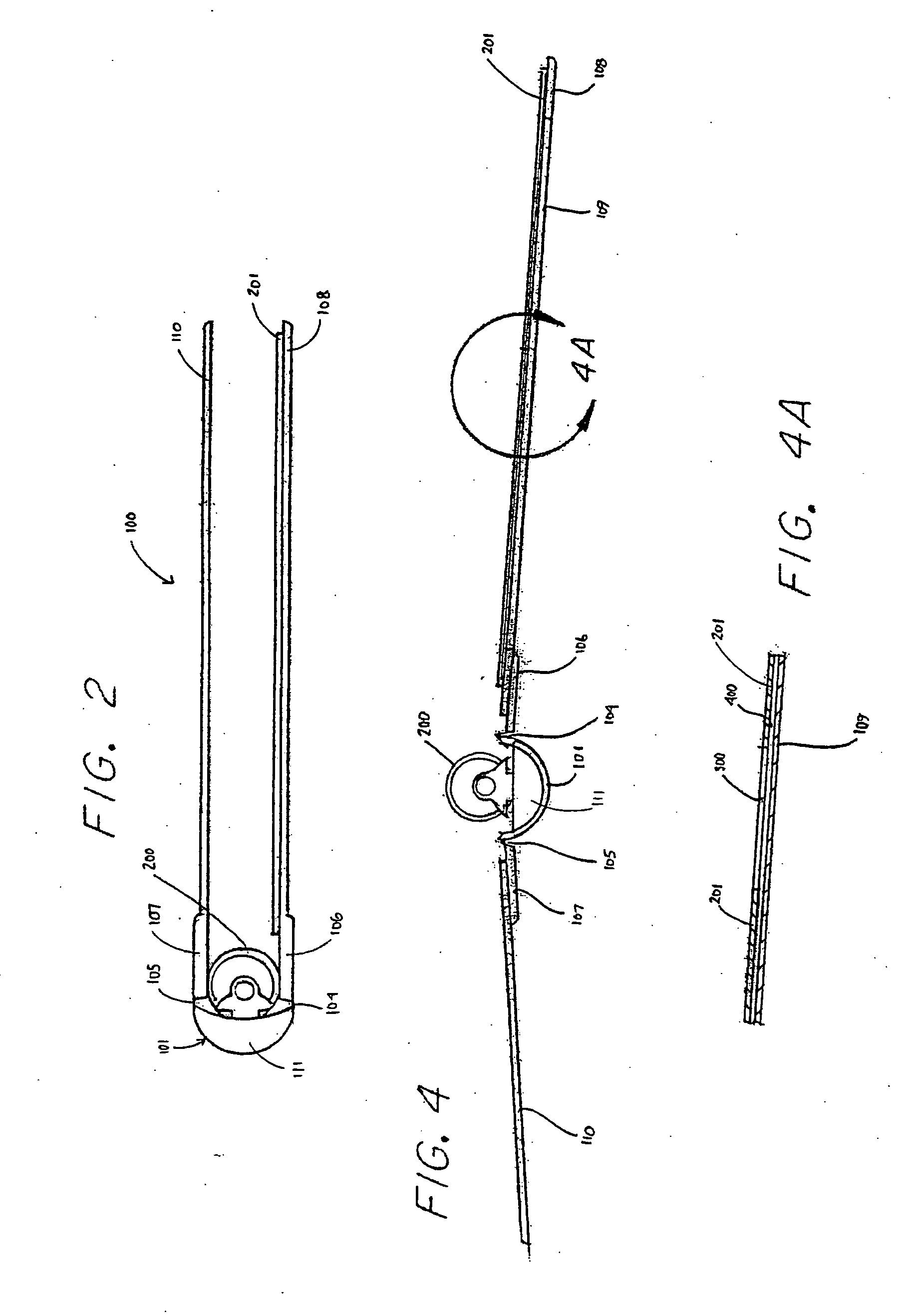
[0016] Continuing with FIG. 1, the binder includes a spine 101 that is composed of a main body coupled to a first flange 106 and a second flange 107 by a first hinge 104 and a second hinge 105, respectively. The front 108 and back cover 110 of the binder 100 are coupled to spine via the first 106 and second flang...


PUM


Abstract

Binders disclosed herein include a front cover, a back cover and a spine interconnecting the front cover and the back cover. The front cover includes a substantially transparent window integral with a first side of the front cover and an inner panel coupled to a second side of the front cover to form a pocket. Visual materials may be inserted into the pocket and be visible through the substantially transparent window.

Description

BACKGROUND [0001] Papers and other media have been stored in portfolios, folders, binders, wire-bound notebooks, and the like. Binders, in particular, are a popular choice of storing media due to their ease of use, storage flexibility, and cost effectiveness. Binders are also desirable because papers or other media may be easily inserted and removed from the binders. Given the broad applications for binders, a wide variety of binders have been developed. For example, some prior art binders include a transparent cover so that visual materials may be visible from the front cover of the binder. Generally, a transparent sheet of flexible material is secured along three sides onto the cover of a binder to form a pocket into which visual presentation sheets may be inserted. However, such arrangements may be somewhat unfinished or unprofessional in their appearance. BRIEF SUMMARY [0002] Exemplary embodiments disclosed herein are directed to a binder having a front cover, back cover, and a ...

Claims


Application Information

Patent Timeline
IPC IPC(8): B42F13/00B42F13/16
CPCB42F13/16B42F13/0066
Inventor YAMAMOTO, NORMANPIOREK, STEVEN K.TENNANT, ROBERT C.KARTEN, STUART A.
Owner AVERY DENNISON CORP
Learn More