
Hair trimmer with rattle dampening structure

a technology of dampening structure and trimmer, which is applied in the direction of metal working apparatus, etc., can solve the problems of increasing friction between parts, affecting the handling quality of trimmer, and rattling noise while interfering with trimmer handling quality,

Active Publication Date: 2005-03-03
MATSUSHITA ELECTRIC WORKS LTD
View PDF11 Cites 7 Cited by
  • Summary
  • Abstract
  • Description
  • Claims
  • Application Information

AI Technical Summary

Benefits of technology

"The present invention provides a rattle-dampening structure for a hair trimmer's comb attachment which is for trim length adjustment. The structure has an unsophisticated design that allows for easy guarantee of product quality by eliminating rattling of the comb attachment. The invention includes an elastic member for elastically pressing the comb attachment for trim length adjustment, in a direction approximately perpendicular to the moving direction of the comb attachment. The elastic member can be disposed in the main body or the comb attachment. The invention also includes guided rail portions and guiding rail portions for stable movement of the comb attachment in a predetermined direction. The invention further includes a pressure receiving element and a receiving groove portion for easy adjustment of the comb attachment. The technical effects of the invention include improved manipulability, enhanced manipability, easy guarantee of product quality, and reduced rattling noise."

Problems solved by technology

However, in the conventional example above, since the cylindrical comb attachment is merely movably engaged with the main body, it rattles in an approximately perpendicular direction to its movable direction, thereby making a rattling noise while interfering the trimmer's handling quality.
Further, also in the area where the protrusion on the main body's exterior surface is inserted in the spiral groove, the cylindrical adjustment element rattles and makes a similar noise.
In this case, in order to eliminate such rattling, if the comb attachment and the main body are made to engage tightly, or otherwise, the spiral groove and the protrusion on the main body's exterior surface are tightly fitted, the friction between the parts would increase, so that precise operation of the cutter becomes more difficult.
Further, in order to mass produce the cutter with features with such subtle dimensional variations, maintaining the product quality becomes a formidable challenge.

Method used


Image

  • Hair trimmer with rattle dampening structure
  • Hair trimmer with rattle dampening structure
  • Hair trimmer with rattle dampening structure

Examples


Embodiment Construction

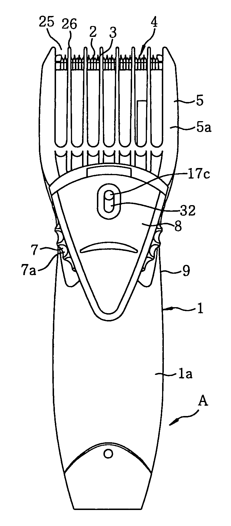
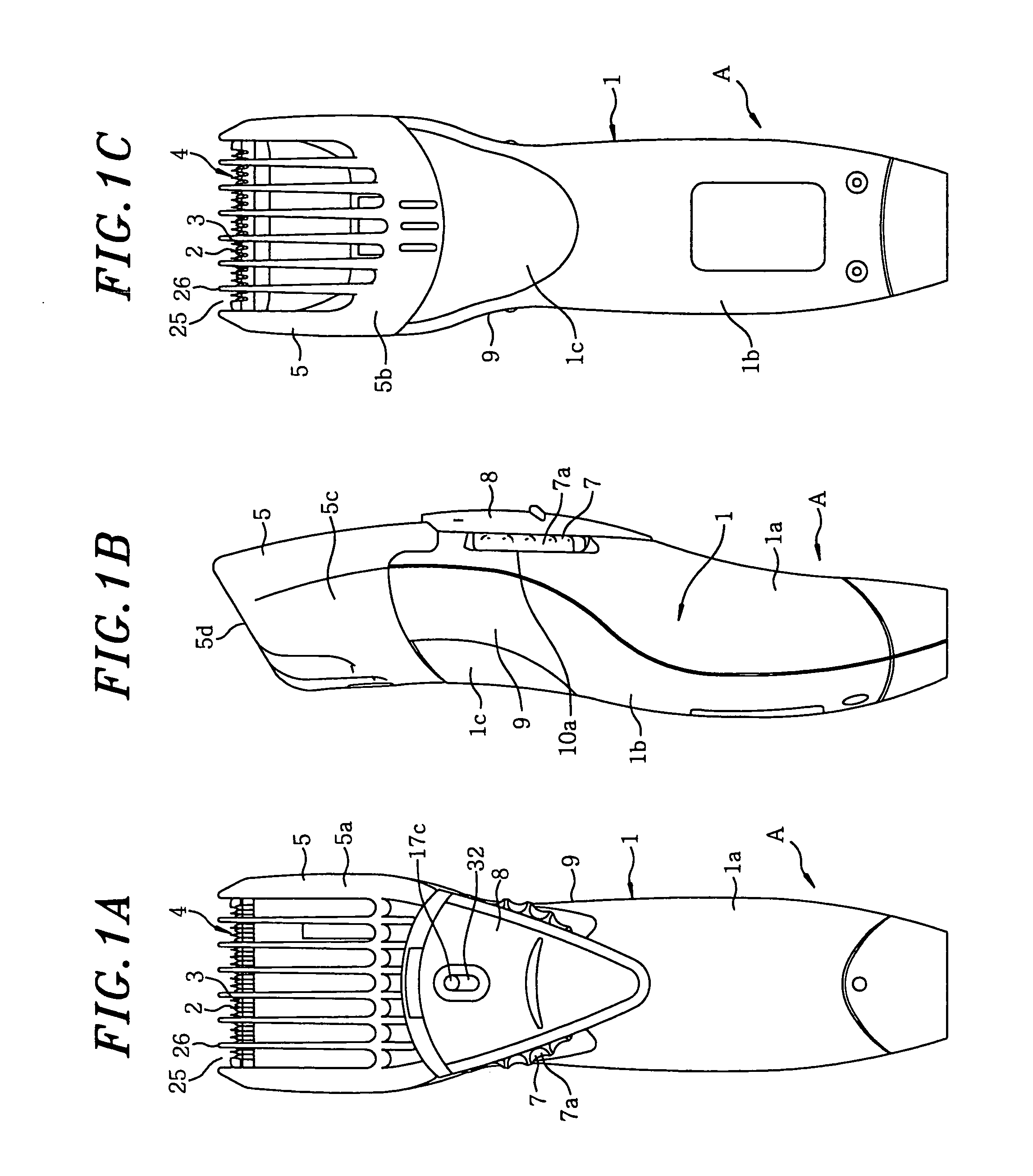
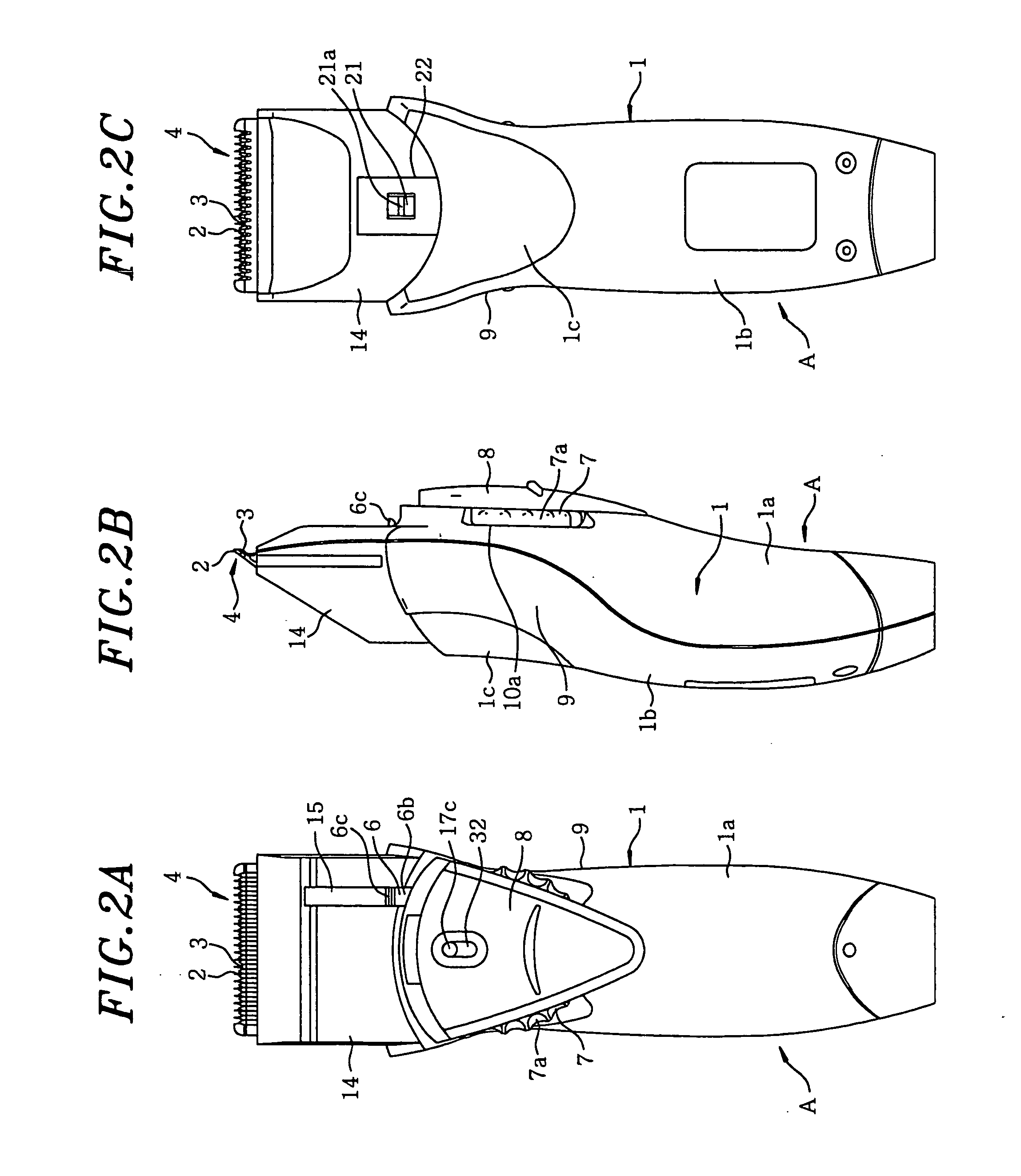
[0033] Hereinafter, the present invention will be described in accordance with a preferred embodiment as illustrated in the accompanying drawings.

[0034] A hair trimmer A is configured such that a cutter block 4 having a stationary blade 2 in combination with a movable blade 3 both of which are comb-shaped and slidably in contact with each other, is protrudingly disposed at one end portion in the lengthwise direction of an approximately cylindrical main body 1 which extends from the one end to the other end portion. The main body 1 is formed as shown in FIGS. 2A to 2C, and among the four side-surfaces established when one end portion where the cutter block 4 is protrudingly disposed is oriented upward so that the opposite end portion points downward, a rotary dial 7 is provided at one of the four side-surfaces in parallel (or approximately parallel) with the corresponding side-surface, and an operation switch 8 for turning on / off an operation of the main body 1 is provided at the ex...


PUM


Abstract

A hair trimmer with a rattle dampening structure, includes an elongated main body; a cutter block having a stationary blade and a movable blade, both of which are comb-shaped and are slidably in contact with each other, the cutter block being protrudingly installed at one end of the main body; a comb-shaped cylindrical comb attachment covering the cutter block such that it is movable in a projected direction of the cutter block; and an elastic member for elastically pressing the comb attachment for trim length adjustment, in a direction approximately perpendicular to a moving direction of the comb attachment.

Description

FIELD OF THE INVENTION [0001] The present invention relates to a rattle dampening structure for a comb attachment of a hair trimmer with a cutter block having comb-shaped reciprocating blades, only one of which is movable. The hair trimmer cuts hair and beard by the operation of the reciprocating blades, over which the comb attachment is placed so that the trim length can be varied. BACKGROUND OF THE INVENTION [0002] Japanese Patent Laid-open Application No. H1-214388 (hereinafter refer to as “Patent 1”) discloses therein a trim length adjusting structure for a conventional hair cutter. In the conventional example described in Patent 1, a cutter block consisting of a stationary and movable blade, both of which are comb-shaped and one of which reciprocates, is protrudingly disposed at one end portion of a main body. A cylindrical comb attachment in a comb shape for trim length adjustment is movably engaged at the portion of the main body where the cutter block is disposed and along t...

Claims


Application Information

Patent Timeline
Patent Type & Authority Applications(United States)
IPC IPC(8): B26B19/10B26B19/04B26B19/20B26B19/42
CPCB26B19/20B26B19/04B26B19/10
Inventor NAKAKURA, MAKOTOOGAWA, HITOSHIYABUUCHI, SEIKO
Owner MATSUSHITA ELECTRIC WORKS LTD
Learn More