
Damper device for mechanical seals

a technology of mechanical seals and dampers, which is applied in the direction of mechanical seals, engine components, mechanical apparatuses, etc., can solve the problems of poor lubricant, thin fluid film between the seals, and very little lubrication

Inactive Publication Date: 2005-02-17
AES ENG
View PDF6 Cites 20 Cited by
  • Summary
  • Abstract
  • Description
  • Claims
  • Application Information

AI Technical Summary

Benefits of technology

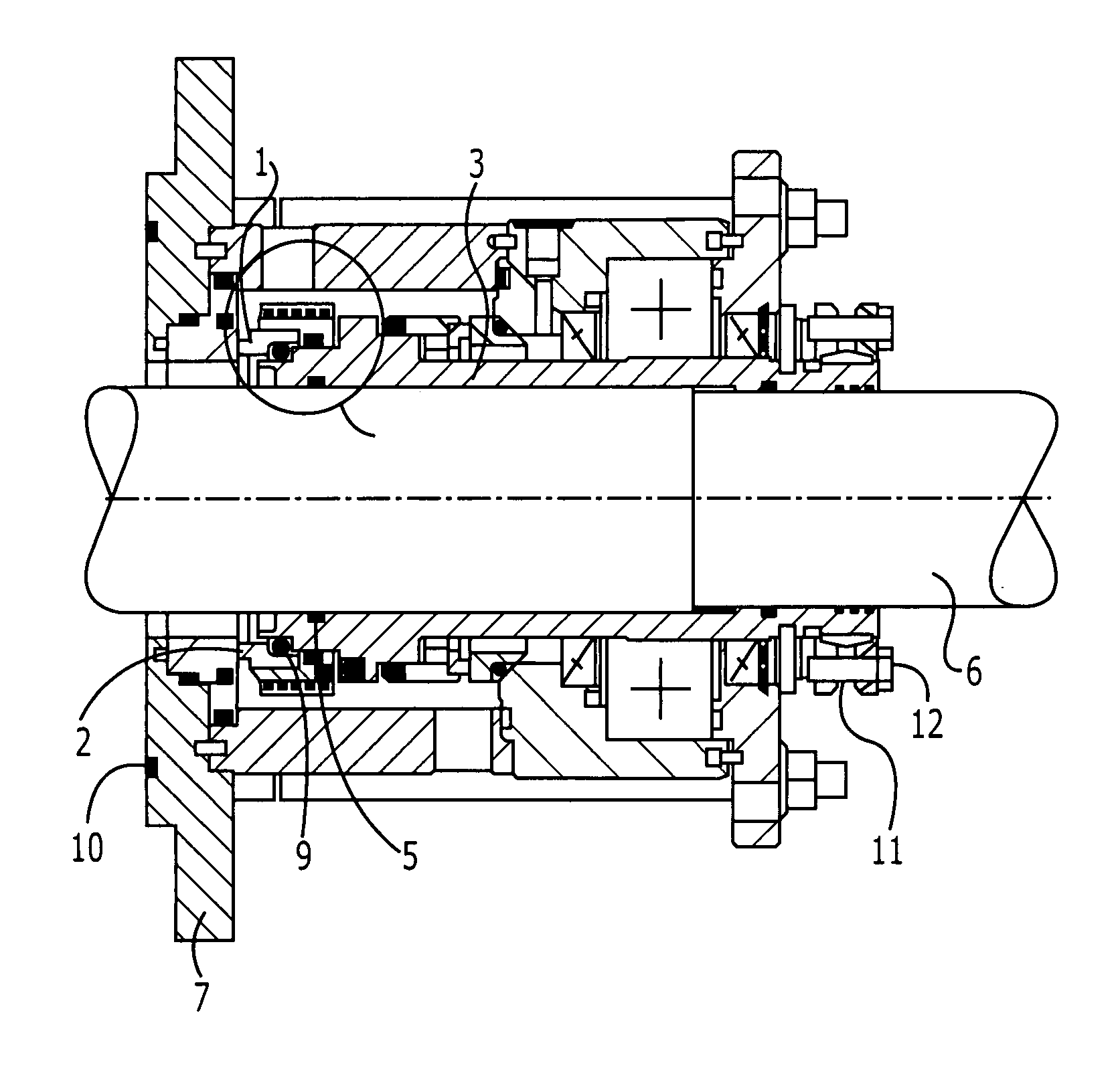
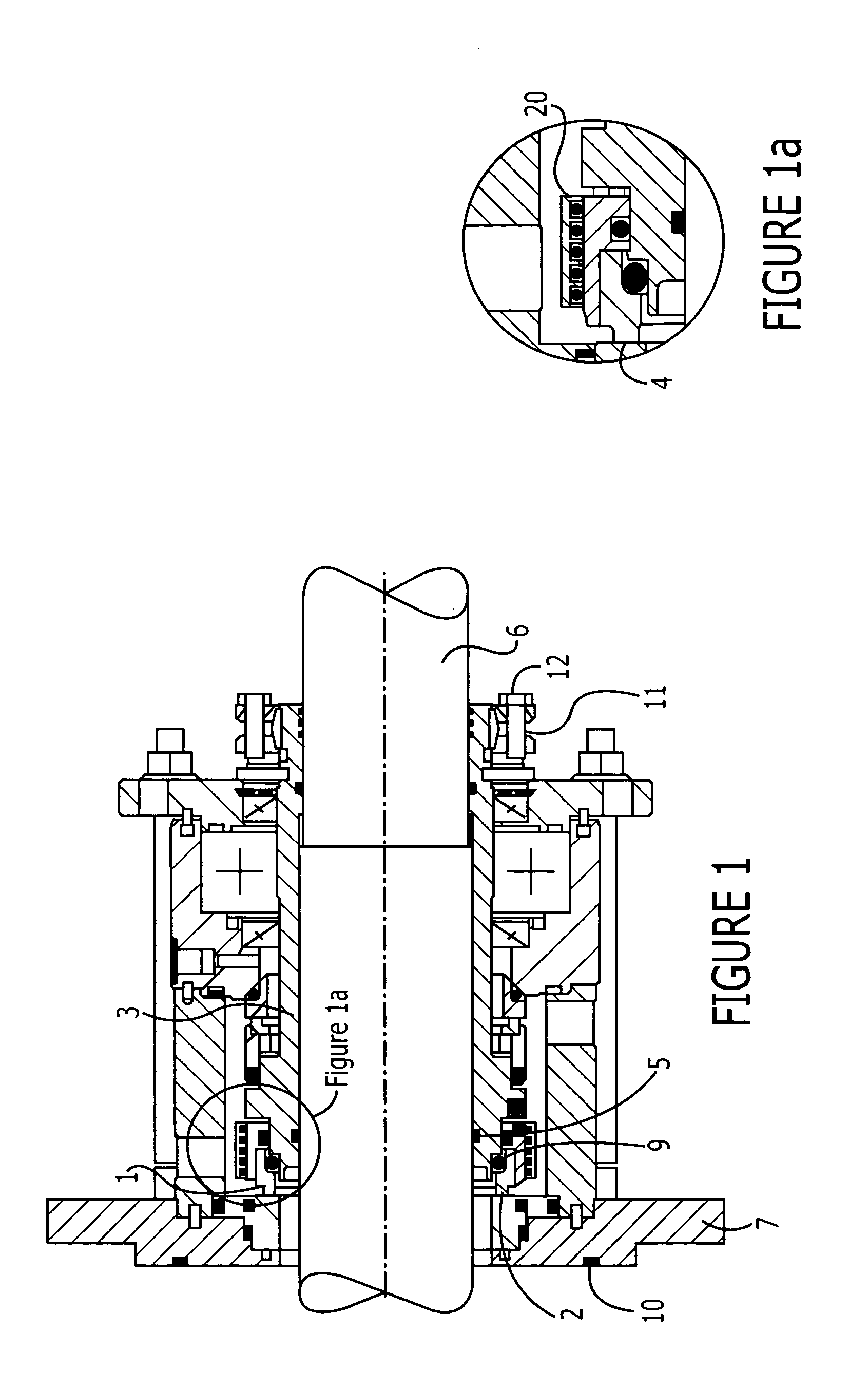
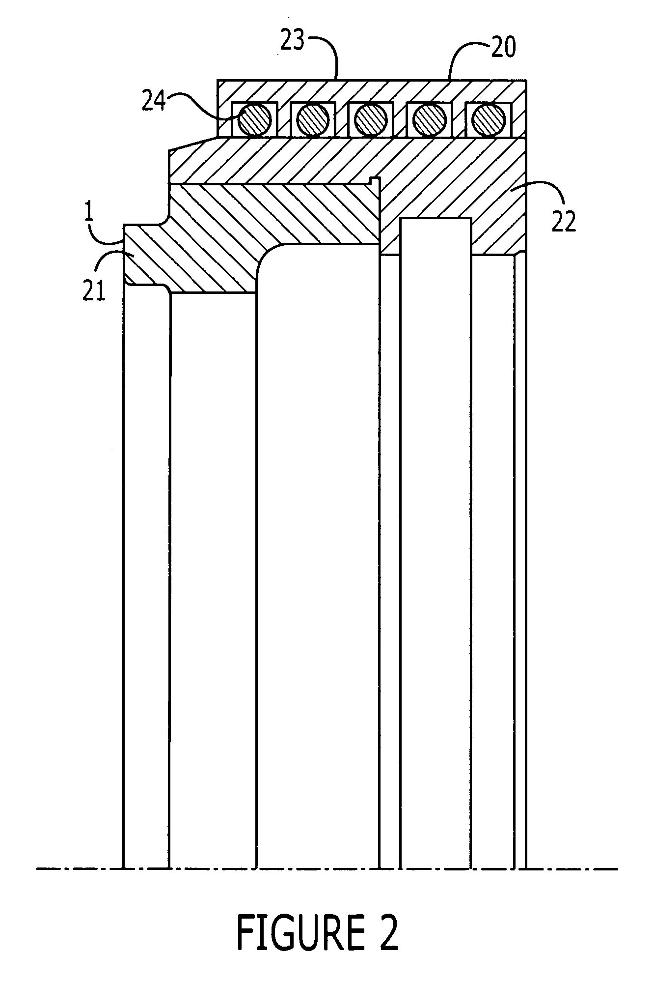
The patent text describes a damper device for reducing noise generated by mechanical seals. The damper device comprises support means and damping means, which are placed in a predetermined gap between the support means and the seal face assembly or the gland plate to minimize the transmission of noise. The damping means can be made of various materials, such as elastomeric, plastic, lip-type seals, damping fluids, or vacuums. The technical effect of this invention is to reduce the noise generated by mechanical seals, making it more comfortable for users of the equipment that incorporates a mechanical seal.

Problems solved by technology

It has been found that a gas film is a poorer lubricant than a liquid fluid film and results in a thinner fluid film between the seal faces of a seal.
Fluid films that provide very little lubrication between the seal faces and a high pitch squeaking sound often occurs.
The noise is undesirable and is most uncomfortable to a user of the equipment that incorporates a mechanical seal.

Method used


Image

  • Damper device for mechanical seals
  • Damper device for mechanical seals
  • Damper device for mechanical seals

Examples


seventh embodiment

[0048]FIG. 8 shows the invention where a support member (112) includes a least one orifice (113) that extends entirely through the support member. The orifice is shaped to allow a set screw (114) to be inserted. The orifice is preferably threaded. The support member is arranged relative to a surface of the rotary seal face component holder (22) such that a predetermined gap is formed between the set screw (114) and the surface of the holder. Damping means in the form of a spring-like member (115) are disposed in the predetermined gap. The spring-like member acts as an energy absorber and is suitable for absorbing noise. Obviously this embodiment of the damper device is suitable for use with a stationary seal face assembly.

eighth embodiment

[0049]FIG. 9 depicts yet another embodiment of the present invention arranged with respect to a rotary seal face assembly. the invention comprises a support member that includes an orifice (113) through which fluid may flow to and from a predetermined gap. Accordingly, the gap (124) may be filled with a damping fluid to absorb noise. Alternatively fluid may be removed from the gap in order to create a vacuum that prevents the transmission of noise produced by the mechanical seal. Further predetermined gaps are formed within which elastomers (125&126) are disposed. The elastomers are used to help seal the predetermined gap containing the damping fluid or vacuum and help further absorb noise. This embodiment may be mounted relative to a stationary seal face assembly.

[0050]FIG. 10 depicts a cartridge seal in which an embodiment of a second aspect of the invention is mounted. In this particular example the support member of the damper device is not arranged with respect to a seal face a...


PUM


Abstract

A damper device for a mechanical seal includes support means arranged relative to a seal face assembly or a gland plate of the mechanical seal such that a predetermined gap is formed between the support means and the seal face assembly / gland plate and also includes damping means disposed in the predetermined gap in order to reduce the transmission of noise produced by the mechanical seal.

Description

RELATED APPLICATION [0001] This application claims priority to UK Patent Application No. GB0312185.2, filed May 28, 2003, the disclosure of which is hereby incorporated herein by reference. FIELD OF INVENTION [0002] This invention relates to damper devices for mechanical seals and mechanical seals comprising such damper devices. The invention particularly relates to damper devices for absorbing noise produced by the mechanical seals, for example noise produced by the seal faces of the mechanical seals due to poor lubrication conditions. BACKGROUND INFORMATION [0003] A mechanical seal comprises a “floating” component and a “static” component. The floating component has a flat annular end face, i.e. a seal face that is directed towards a complementary seal face of the static component. The components are urged together, usually by means of one or more spring members, in order to close the seal faces together to form a sliding seal. [0004] When a mechanical seal is in use then either t...

Claims


Application Information

Patent Timeline
Patent Type & Authority Applications(United States)
IPC IPC(8): F16J15/34F16J15/38
CPCF16J15/3476F16J15/38F16J15/348F16F15/04F16J15/3484
Inventor ROBERTS, TOMBOOTH, CHRIS
Owner AES ENG
Learn More