
Vented bottle

a bottle and venting technology, applied in the field of baby bottles, can solve the problems of spitting up, affecting the quality of baby food, and forming a partial vacuum within the bottle, and achieve the effect of reducing or eliminating gas and spitting up

Inactive Publication Date: 2005-02-17
JMBH HLDG LLC
View PDF96 Cites 36 Cited by
  • Summary
  • Abstract
  • Description
  • Claims
  • Application Information

AI Technical Summary

Benefits of technology

[0010] It is an object of the present invention to provide a bottle that reduces or eliminates gas and spitting up during feeding of an infant.
[0011] It is another object of the present invention to provide such bottle that reduces or eliminates nipple collapse.
[0013] It is yet a further object of the present invention to provide such a bottle with a nipple that promotes latching on to the areola region of the nipple.
[0014] It is still a further object of the present invention to provide such a bottle that facilitates manipulation and handling of the bottle.

Problems solved by technology

During use, however, as the baby sucks on the nipple and withdraws the fluid, a partial vacuum is formed within the bottle.
This vacuum can make feeding more difficult, by requiring the baby to suck with much greater force, which can discourage the baby and cause it to stop feeding sooner than desired.
Moreover, the vacuum can cause the nipple to collapse.
However, this bottle suffers from the drawback of venting during feeding whereby the air mixes with the liquid that is in proximity to the nipple, is ingested by the infant, and causes greater risk of gas and spitting up.
Due to the significant differences in the shape and function between a woman's breast and conventional baby bottle nipples, babies experience difficulty when switching between breast-feeding and bottle-feeding.
This can cause a baby to fail to take formula from a baby bottle nipple.
Likewise, babies can grow accustomed to the shape and function of a particular conventional baby bottle nipple, creating difficulty for the baby to return to breast-feeding.
This can cause a baby to fail to take milk from a woman's breast because of a developed preference for the shape, texture and function of the baby bottle nipple.
The disclosed nipple suffers from the drawback of having three segments or areas that do not simulate the shape and function of a woman's breast.
Moreover, such nipples suffer from the drawback of collapsing.

Method used


Image

  • Vented bottle
  • Vented bottle
  • Vented bottle

Examples


Embodiment Construction

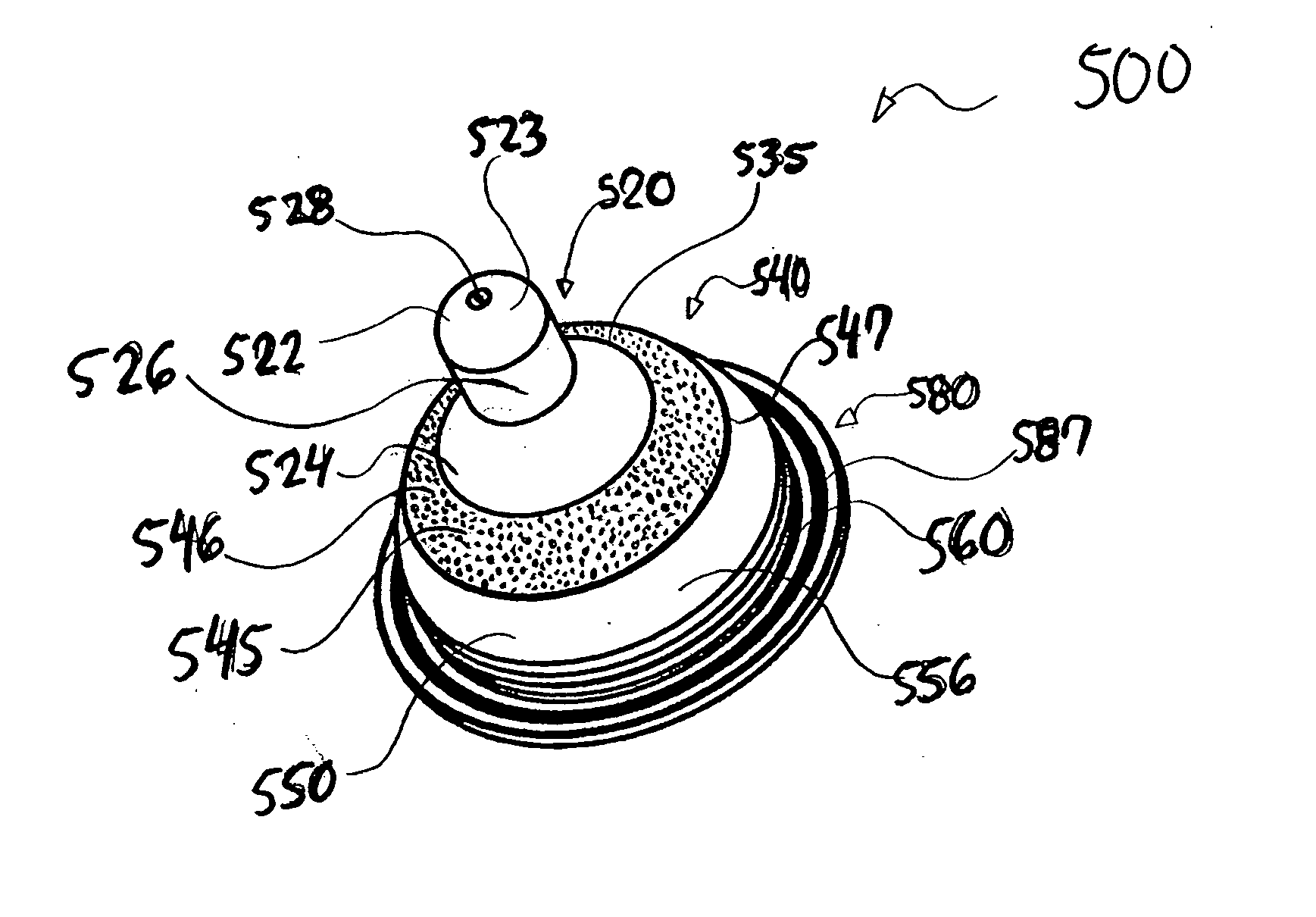
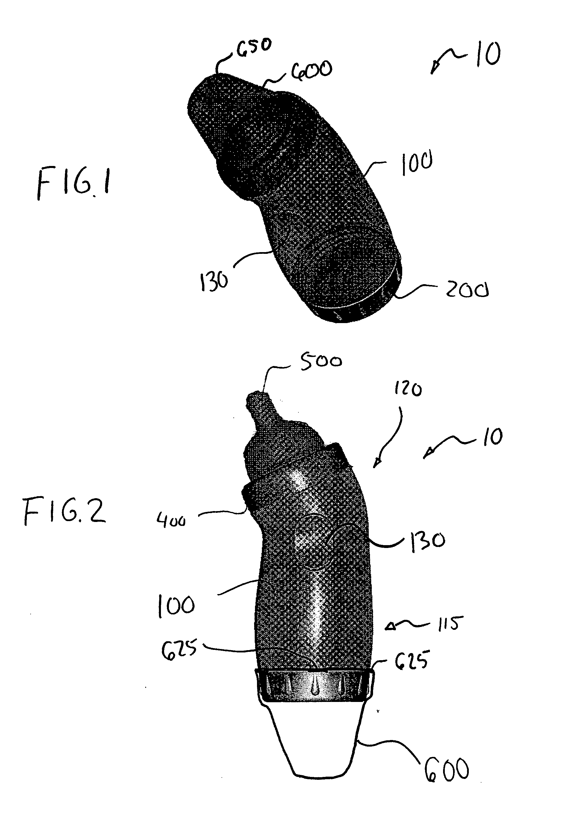
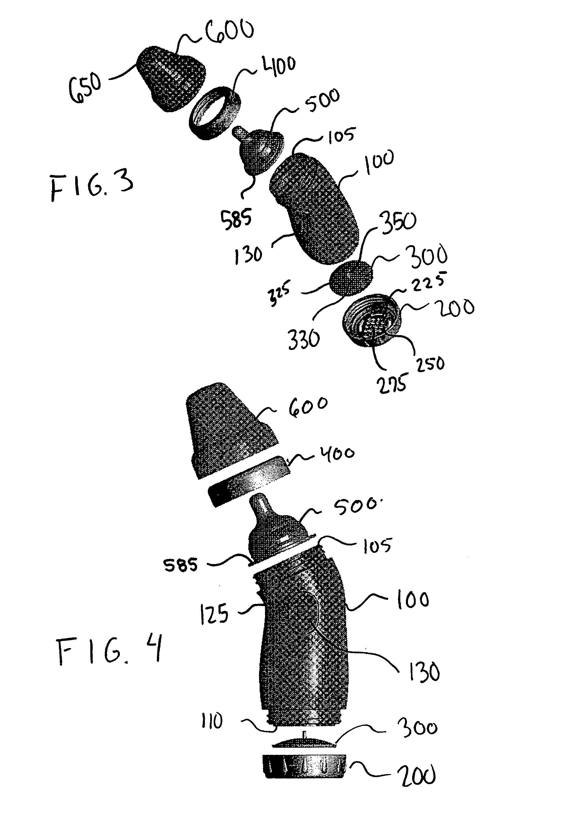
[0038] Referring to the figures and, in particular, FIGS. 1 through 4, the bottle assembly of the present invention is generally referred to by reference numeral 10. The bottle assembly 10 includes a bottle 100, a bottom cap 200, a vent 300, a nipple ring 400, a nipple 500, and a hood 600.

[0039] Bottle 100 has a first open end 105 and a second open end 110. Preferably, bottle 100 has an angled shape, i.e., the plane in which the opening of first open end 105 is substantially disposed intersects with the plane in which the opening of second open end 110 is substantially disposed. The angle between first open end 105 and second open end 110 facilitates manipulation and feeding for the infant, as well as improving venting within the bottle, as will be described later. Preferably, the angle of the bottle 100 is between about 10° to 90°, more preferably between about 20° to 45°, and most preferably about 25°.

[0040] Bottle 100 preferably has a lower portion 115 that narrows towards uppe...


PUM


Abstract

A vented bottle is provided. The vent is remote from the nipple. The bottle has a nipple simulating the shape, surface geometry and function of a woman's breast is provided. The nipple has a stem and a base. The base can have an areola region and a bulbous region. The areola region is positioned between the stem and the bulbous region, and can simulate the areola of a woman's breast. The bulbous region can simulate the region of a woman's breast surrounding the areola. The areola region can have a texture or surface geometry that is different from the texture or surface geometry of the stem or bulbous region.

Description

RELATED APPLICATION [0001] This application is a continuation-in-part of copending application Ser. No. 10 / 272,475, filed Oct. 16, 2002, which is a continuation-in-part of application Ser. No. 10 / 054,510, filed Nov. 13, 2001, which claims priority in application Ser. No. 29 / 152,115, filed Oct. 29, 2001, the disclosures of which are incorporated in their entirety herein by reference. This application is also a continuation-in-part of copending application Ser. No. 09 / 906,320, filed Jul. 16, 2001, which claims priority in U.S. application Ser. No. 29 / 121,308, filed Apr. 5, 2000 and issued as U.S. Design Pat. No. 445,193, the disclosures of which are incorporated in their entirety herein by reference. This application is also a continuation-in-part of copending application Ser. No. 09 / 639,508, filed Aug. 16, 2000, which is a divisional application of application Ser. No. 09 / 209,070 filed on Dec. 10, 1998 and issued as U.S. Pat. No. 6,138,710, the disclosures of which are incorporated i...

Claims


Application Information

Patent Timeline
IPC IPC(8): A61J9/00A61J9/04A61J11/00B26F1/02B26F1/24
CPCA61J9/04A61J11/0035B26F1/24A61J11/045B26F1/02A61J11/005
Inventor LIEBERMAN, JOSHUAROUSSO, JOHNBROWN, JOEL
Owner JMBH HLDG LLC
Learn More