
ECG diagnostic system and method

a technology of ecg and diagnostic system, which is applied in the field of system and method of ecg diagnosis for patients with implanted heart stimulation devices, can solve problems affecting patient safety and care, and achieve the effects of preventing life-threatening bradyarrhythmias, eliminating erroneous diagnoses of conduction block, axis deviation, and myocardial infarction, and improving interpretation of repolarization changes associated with ecg

Inactive Publication Date: 2005-02-03
KLIGFIELD PAUL D +1
View PDF7 Cites 58 Cited by
  • Summary
  • Abstract
  • Description
  • Claims
  • Application Information

AI Technical Summary

Benefits of technology

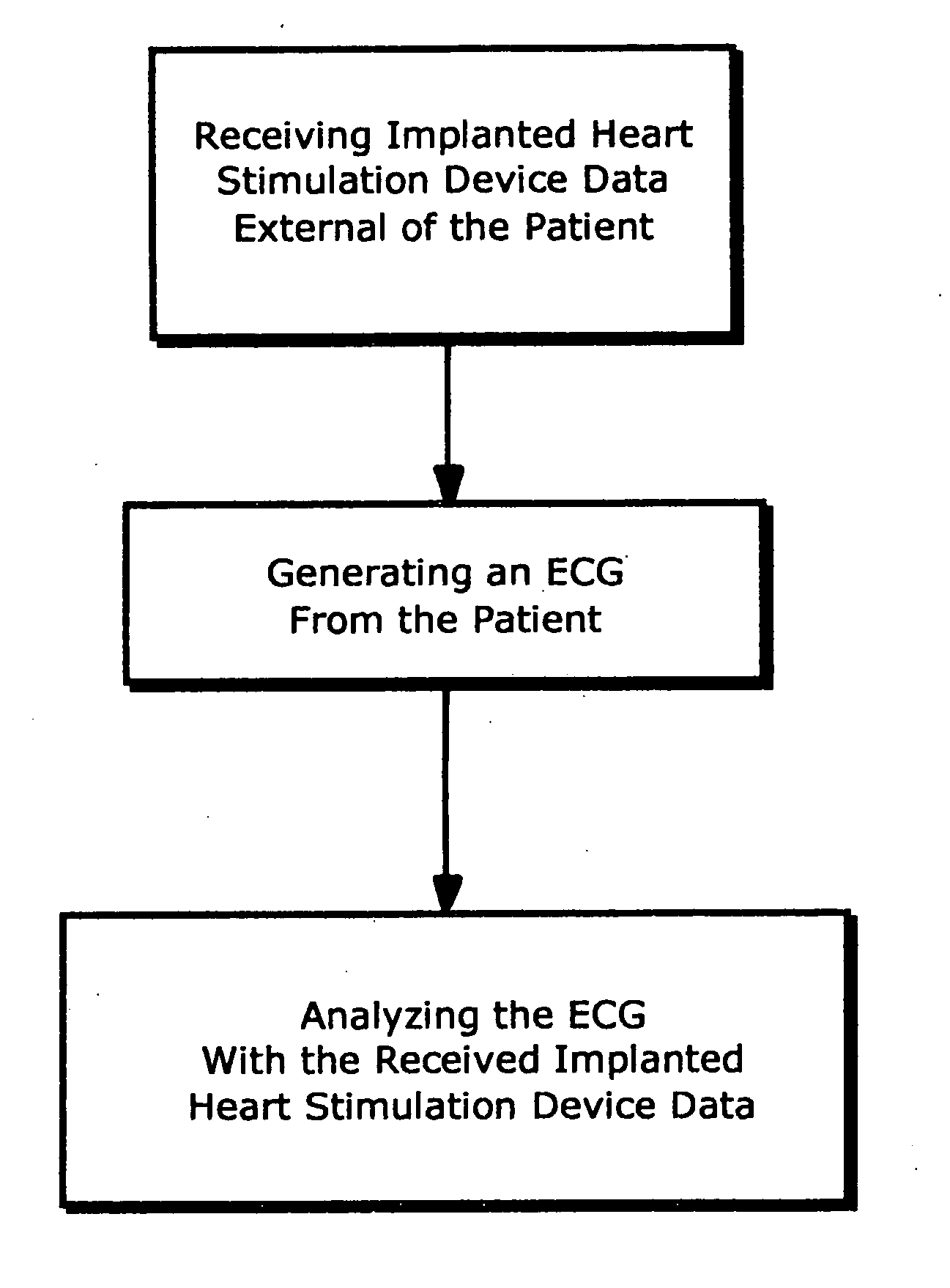
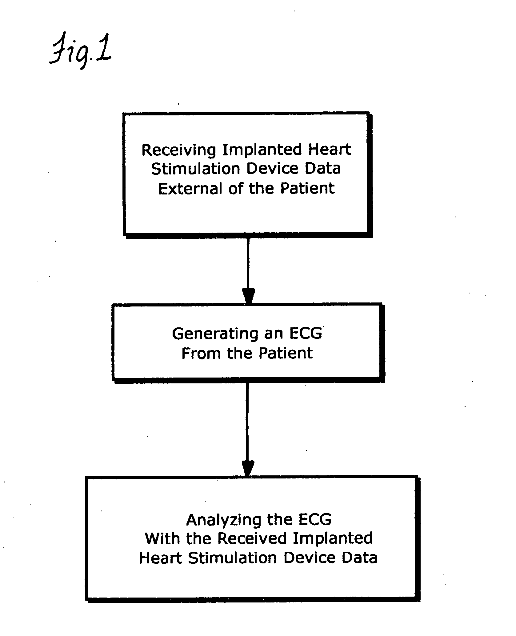
[0025] In accordance with one aspect of the invention, a system and method are provided that enable communication of data or information related to a heart stimulation device, e.g., an implanted cardiac pacemaker or defibrillator, to an external reader as may be incorporated in an electrocardiograph apparatus to improve interpretation capability of the electrocardiographer and to enhance preliminary computer-based analysis of pacemaker function by the electrocardiograph. Transmitted information may include, but is not limited to, pacemaker identification, active mode of behavior, and sensing and pacing markers.
[0027] As earlier discussed, erroneous diagnosis of pacemaker sensing and capture adversely affects patient safety and care. When recognized with the system and method herein, pacemaker undersensing or oversensing can be corrected to regulate cardiac rhythm in the prescribed manner. Appropriate recognition of failure to pace or to capture can prevent life-threatening bradyarrhythmias in susceptible patients. Detection and recognition of occult pacing or pacing fusion can eliminate erroneous diagnoses of conduction block, axis deviation, and myocardial infarction. Detection and recognition of normal intermittent pacemaker function, previously undetectable on the surface electrocardiogram, can improve interpretation of repolarization changes associated with pacemaker memory effect. Anticipation of pacemaker battery end-of-life can prompt needed generator replacement that might be prevented by failure to undergo regular transtelephonic or office based pacemaker monitoring. The system and method herein employed, in one aspect, routine 12-lead electrocardiography as an efficient location for communication of pacemaker behavior. Accurate recognition of pacemaker function and dysfunction during routine electrocardiography will reduce the risk of serious arrhythmic events, which in turn should be cost-effective, in patients with heart disease.

Problems solved by technology

As earlier discussed, erroneous diagnosis of pacemaker sensing and capture adversely affects patient safety and care.

Method used


Image

  • ECG diagnostic system and method
  • ECG diagnostic system and method
  • ECG diagnostic system and method

Examples


second embodiment

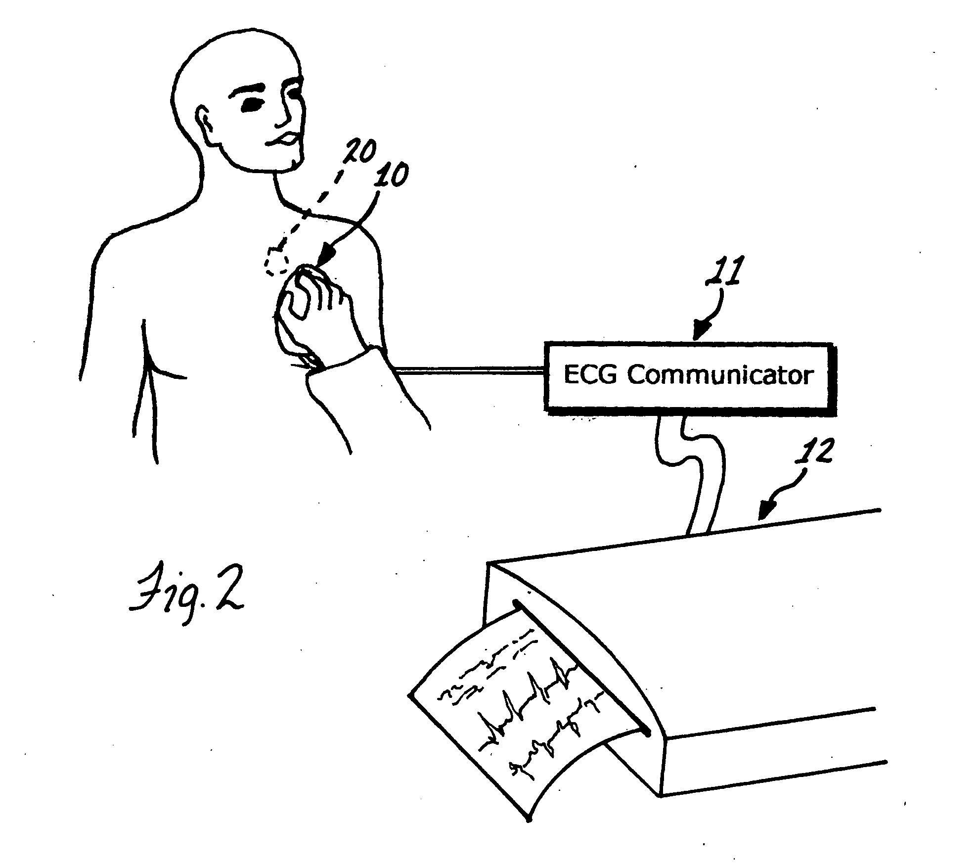
[0034] A second embodiment, one which permits a more detailed interrogation of an implanted pacemaker, can be described with reference to FIG. 2. A patient is shown in whom a pacemaker 20 has been implanted. Also shown is an electromagnetic wand 10 that is designed such that it can be placed on the skin directly over the implanted pacemaker. The wand and pacemaker each have coils of wire contained within them that serve as antennas in close proximity to each other when the wand is properly placed. In operation, the button on the wand is depressed to command a transmission by the pacemaker. The pacemaker receives the command and transmits data back to the wand. These data may include, but are not limited to: pacemaker manufacturer and type; pacing mode, whether DDDR, DDD, DDIR, DDI, VVIR, VVI, AAIR, AAI, or other; any special features that have been programmed on, such as antitachycardia, rate responsive, autocapture, mode switch, PVC response, etc; pacing parameters including lower ...

third embodiment

[0037] In a third embodiment, the wand is eliminated and the pacemaker transmits status data and marker signal directly to the ECG communicator by radio frequency (RF) transmission using the pacemaker power source. The distance between the patient and said ECG communicator in this embodiment could be, for example, 10 feet. The transmitter frequency could be, for example, 420 MHz, a frequency designated by FCC for medical applications. A command to transmit said data and signal is transmitted directly from the ECG communicator to the implanted pacemaker, using the same frequency.

fourth embodiment

[0038] In a fourth embodiment, the pacemaker status and marker data are not transmitted, but are superimposed on a suitable carrier and delivered directly to the pacemaker intracardiac electrodes. The signal power is well beneath that of a pacing stimulus and has no physiological effect. However, the signal can be detected using electrodes on the skin, including in particular the standard ECG electrodes. In this embodiment, the cable from the standard ECG electrodes is connected directly to the ECG communicator, which has additional receiver circuitry for separating the high-frequency carrier-based status and marker signal from the lower-frequency electrocardiographic signal. The status data, marker signal, and ECG are then delivered to the ECG machine for printing.

[0039] As is apparent, the systems disclosed herein all include information or data acquiring means that allow an electrocardiographer to easily acquire information or data relating to the implanted heart stimulator devic...


PUM


Abstract

A system and method are disclosed for providing enhanced ECG diagnosis for patients having an implanted heart stimulation device. The system acquires data relating to the device for use in the ECG diagnosis. In one preferred form, data is transferred from an implanted transponder programmed with the data to a standard ECG monitoring electrode applied to the patient's chest, and the read out generated by the ECG machine includes the transferred data.

Description

FIELD OF THE INVENTION [0001] This invention relates to a system and method of ECG diagnosis and more particularly, to an ECG diagnostic system and method for a patient with an implanted heart stimulation device. BACKGROUND OF THE INVENTION [0002] Electrocardiographic (ECG) diagnosis is often difficult in patients with pacemakers, and it is becoming more difficult with increasing complexity of modern pacemaker function and with lead systems that reduce the magnitude of the pacemaker signal on the body surface. Diagnostic difficulties include simple detection of pacemaker presence, recognition of prevalent pacemaker mode, interpretation of pacemaker sensing and capture, and understanding of specialized pacemaker self-testing behavior. Preliminary computer-based misinterpretation of pacemaker function may mislead the electrocardiographer, whose ability to recognize normal and abnormal pacemaker behavior varies widely. [0003] There is no present method by which pacemakers communicate t...

Claims


Application Information

Patent Timeline
IPC IPC(8): A61B5/00A61B5/0402A61N1/372
CPCA61B5/0006A61B2560/0219A61B5/0402A61B5/318
Inventor KLIGFIELD, PAUL D.ARZBAECHER, ROBERT
Owner KLIGFIELD PAUL D
Learn More