
Pneumatic front suspension assembly for industrial vehicle

a technology for industrial vehicles and front suspensions, which is applied in the direction of shock absorbers, mechanical devices, transportation and packaging, etc., can solve the problems of limited chassis relative to axle travel, inadequate axle guidance, and limited flexability

Inactive Publication Date: 2004-07-29
RENAULT TRUCKS
View PDF16 Cites 8 Cited by
  • Summary
  • Abstract
  • Description
  • Claims
  • Application Information

AI Technical Summary

Benefits of technology

[0027] In addition, the anti-roll bar couples the flexing of the two suspensions thus ensuring an increase in anti-roll rigidity, such rigidity being adaptable to suit the usage of the vehicle.

Problems solved by technology

Specifically, the travel of the chassis relative to the axle is relatively limited, because it depends on the flexing capability of the leaf spring.
To present sufficient strength, this leaf must be sufficiently thick which limits its ability to flex.
On the other hand, the leaf spring's ability to flex leads to inadequate guidance of the axle, since the leaf can twist due to its relative thinness compared with its width.
This solution has the disadvantage of producing a poor kinematic linkage, because the transverse link moves in a circular arc during the vertical motions of the axle.
The movement of this transverse link therefore induces transverse movements of the axle which adversely affect road holding.
In order to bear transverse loads, the presence of a transverse link is necessary, with the disadvantages of the corresponding kinematic linkage previously described.
However, this solution has the disadvantage inherent in the use of a leaf spring, that is a short travel and a tendency to allow transverse motions that compromise road holding.

Method used


Image

  • Pneumatic front suspension assembly for industrial vehicle
  • Pneumatic front suspension assembly for industrial vehicle
  • Pneumatic front suspension assembly for industrial vehicle

Examples


Embodiment Construction

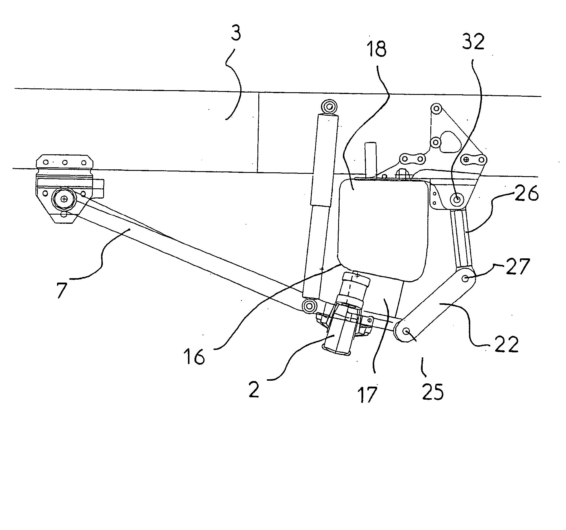
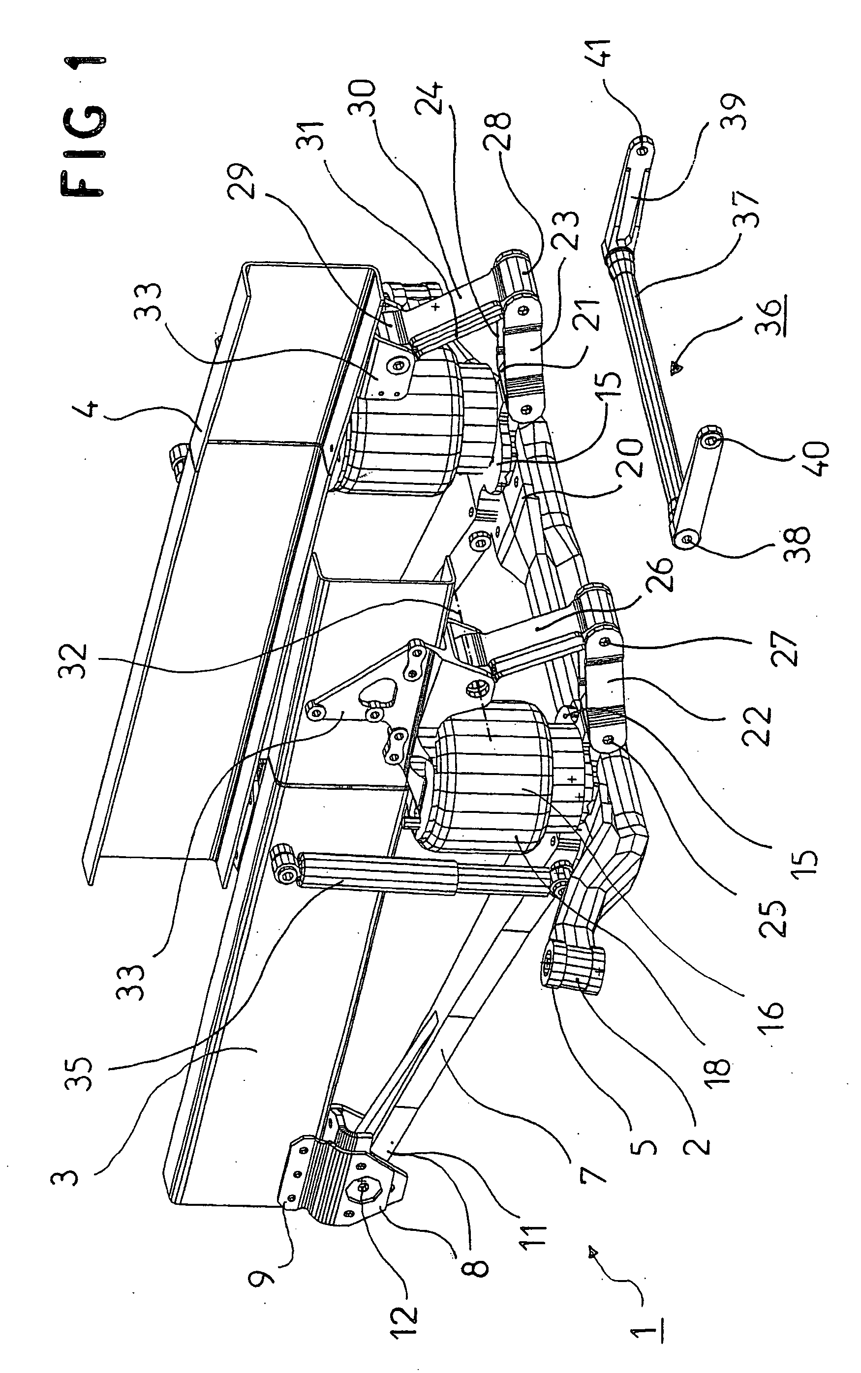
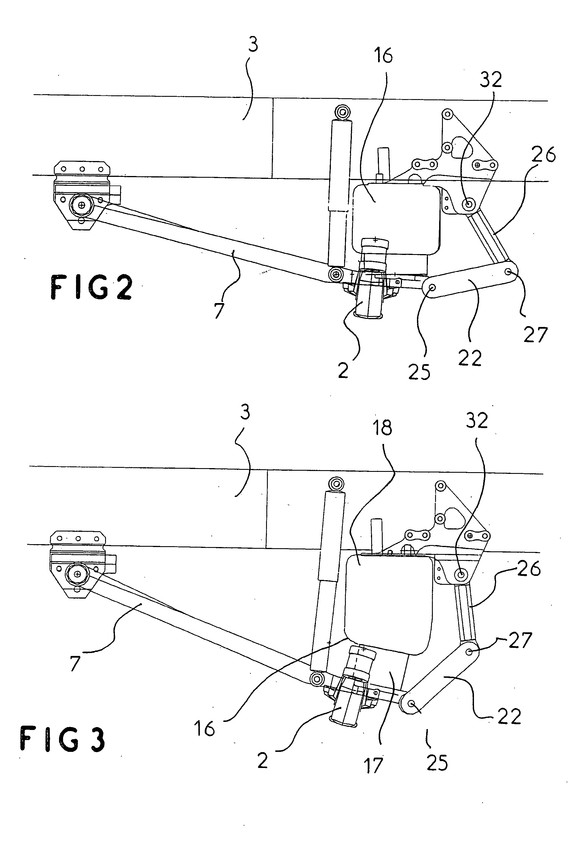
[0013] The invention therefore concerns a pneumatic front suspension assembly for industrial vehicles. In a known manner, this suspension assembly comprises:

[0014] a front axle linked to a pair of side members;

[0015] a pair of air bags for adjusting the height of the axle relative to the side members.

[0016] In accordance with the invention, the suspension assembly is characterized in that it comprises on each side:

[0017] a rigid arm, of which one extremity is articulated relative to the side members and of which the other extremity receives the axle and the bottom part of one of the air bags;

[0018] a pair of links mutually articulated about a pin substantially parallel to the axle, one of these links, the upper link, being articulated relative to the side member, the other link, the lower link, being articulated relative to the rigid arm.

[0019] The suspension assembly also comprises a basically U-shaped additional element forming an anti-roll bar. This anti-roll bar comprises:

[0020]...


PUM


Abstract

A pneumatic front suspension assembly for an industrial vehicle comprises: a front axle linked to a pair of side-members, and a pair of airbags for adjusting the height of the axle relative to the side-members. On each side, there is provided a rigid arm whereof one end is articulated relative to the side-members, and the other end receives the axle and the lower part of the suspension air bags; a pair of connecting rods mutually articulated about a pin substantially parallel to the axle, one of said connecting rods, the upper connecting rod, being articulated relative to the side-member, the other connecting rod, the lower connecting rod, being articulated relative to the rigid arm, and a generally U-shaped additional element, forming an anti-roll bar, and including a transverse rod linked to the lower connecting rods at their articulation points with the rigid arms, and branches located on either side of the transverse rod, and linked to the lower connecting rods.

Description

[0001] The invention concerns the field of industrial vehicles. It concerns more particularly vehicles with a rigid front axle associated with a pneumatic suspension device. More specifically it is aimed at a suspension assembly that provides optimal guidance of the front axle while allowing the axle considerable vertical travel.PRIOR ART[0002] In general, the front suspension of a vehicle links the front axle to the chassis via an elastic unit and shock absorbers. It is common for industrial vehicles to be fitted with pneumatic suspensions which provide greater comfort and other advantages over purely mechanical suspensions. A pneumatic suspension therefore mainly comprises an air bag fixed to both the axle and the chassis. More precisely, the air bag is linked to the side members on each side of the chassis. By appropriately controlling the air bag the height of the side members can be adjusted relative to the axle.[0003] Various solutions have already been proposed to produce pne...

Claims


Application Information

Patent Timeline
IPC IPC(8): B60G7/00B60G9/00B60G11/27B60G21/05
CPCB60G7/00B60G9/003B60G11/27B60G2202/152B60G2200/23B60G2200/31B60G2202/135B60G21/05
Inventor RENAUDOT, JEROME
Owner RENAULT TRUCKS
Learn More