Massage apparatus comprising at least one roller driven positively in rotation

Inactive Publication Date: 2003-04-17
CNLP SA
View PDF9 Cites 24 Cited by
  • Summary
  • Abstract
  • Description
  • Claims
  • Application Information

AI Technical Summary

Benefits of technology

[0028] In apparatus such as this, at least one of the transverse surfaces consists of the periphery of a roller driven positively in rotation. The suction circuit opens into the chamber and makes it possible to create suction when the apparatus is applied against the body of the patient, which suction tends to form a fold of skin pressing against the transverse surfaces.

Problems solved by technology

A gadget such as this, of simple design, is relatively tricky to use, is difficult to displace over the body of the patient and simply exerts a "suction cup" action.
The solutions proposed in those documents lead to assemblies which are complicated, tricky to operate and not entirely satisfactory.
In such an embodiment, the two rollers always rotate in the same direction and at the same speed, which means that it is not possible to imagine adapting their action according to the treatments which may sometimes demand different operating conditions.
In consequence, there is now the problem of having multifunction apparatus in which it is possible to be able to adjust and possibly vary the speed of the rollers one with respect to the other and / or their direction of rotation, so as to obtain top quality treatment even with less suction.
There is also the problem of being able periodically to reverse the direction of rotation of one of the rollers with respect to the other during treatment.
In consequence, there is therefore the problem of producing apparatus which makes it possible to monitor the pressure exerted by the rollers on the fold of skin, the amount of suction exerted in the chamber and the speed of rotation of one or both rollers, these rollers rotating either at the same speed or at different speeds, and possibly having a direction of rotation that is periodically reversed.
Likewise, there is also the problem of being able to incorporate into the said apparatus means that will allow the effect of the treatment to be viewed.
Finally, there is the problem of being able to produce motorized apparatus which is as compact as possible and easy to handle.

Method used


Image

  • Massage apparatus comprising at least one roller driven positively in rotation
  • Massage apparatus comprising at least one roller driven positively in rotation
  • Massage apparatus comprising at least one roller driven positively in rotation

Examples


Embodiment Construction

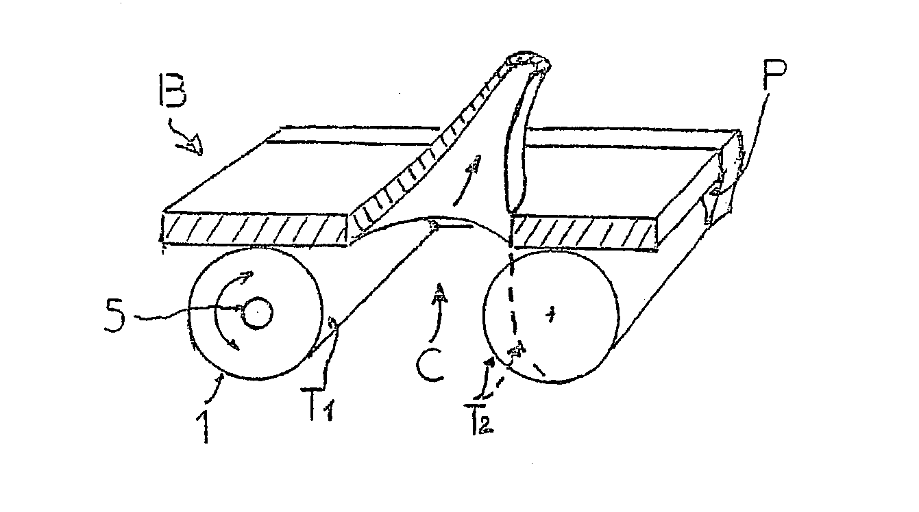
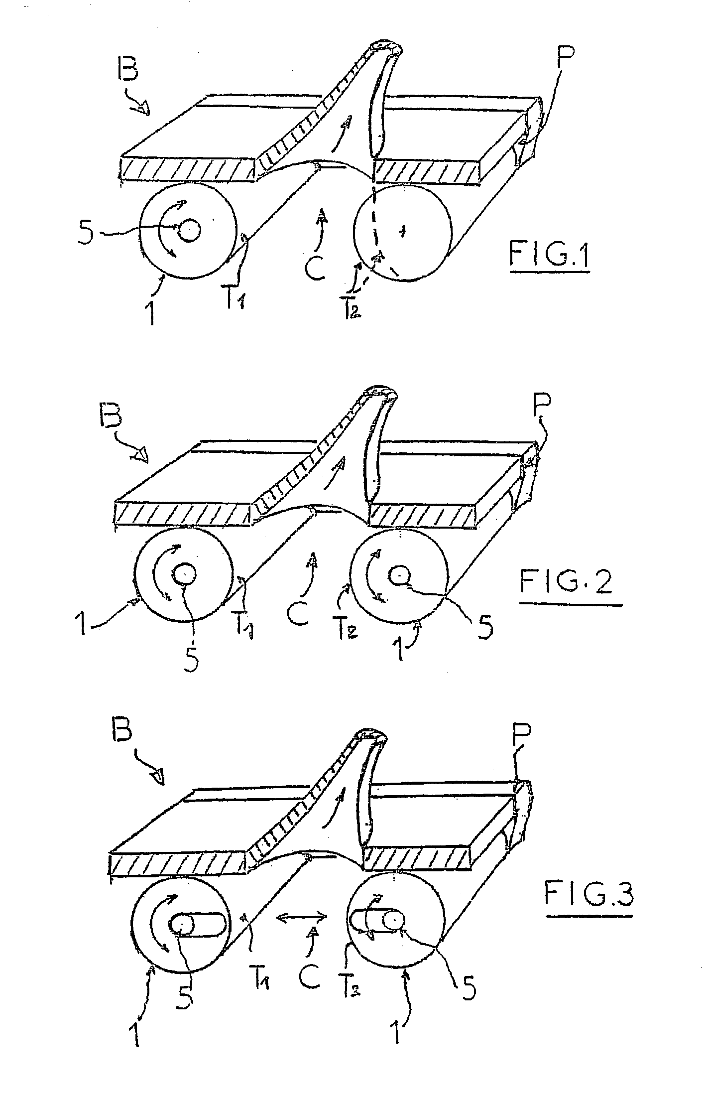
[0081] FIGS. 1 to 3 illustrate, schematically and in perspective, various general forms of massage apparatus produced according to the invention.

[0082] In general, this massage apparatus is of the type whereby an action of suction and of mobilizing the skin tissue is exerted on the subject.

[0083] This apparatus consists of a treatment head proper, connected to a suction circuit and which comprises a box (B) which can be operated manually, comprising an internal chamber (C) open at its base. This chamber (C) is defined by two fixed side walls (P1, P2) and two transverse surfaces (T1, T2) arranged facing one another between the two side walls.

[0084] At least one of these transverse surfaces (T1, T2) consists of the periphery of a roller, denoted by the general reference (1), driven positively in rotation. The suction circuit opens into the chamber (C) and makes it possible to create suction when the apparatus is applied to the body of the patient, which suction tends to form a fold of...


PUM


Abstract

Massage apparatus consisting of a treatment head connected to a suction circuit, the said treatment head comprising a box (B) that can be operated manually, comprising an internal chamber (C) open at its base, which chamber is defined by two fixed side walls (P1, P2) and two transverse surfaces (T1, T2) arranged facing one another between the two side walls (P1, P2), at least one of these surfaces (T1) consisting of the periphery of a roller (1) driven positively in rotation, the suction circuit opening into the said chamber (C) and making it possible to create suction when the apparatus is applied against the body of the patient, which suction tends to form a fold of skin pressing against the transverse surfaces (T1, T2), characterized in that the positive drive of the roller (1) is obtained via a geared motor unit mounted fixed and coaxially inside it, and in which the output shaft (5) of the reduction gear comprises means of coupling to the said roller (1), the said apparatus being associated with means for adjusting the speed and / or direction of rotation of the motorized roller(s) and the amount of suction, possibly varying this, and doing so during operation.

Description

[0001] The present invention relates to a new type of massage apparatus that can be used with equal ease on human beings and on animals (horses, cattle, etc.), and more particularly to massage apparatus in which an action of sucking and mobilizing the skin tissue is performed on the subject.PRIOR ART[0002] Various massage techniques have been used to date, depending on the treatment to be performed, but it can be said that they all involve exerting on the subject stresses which involve phenomena of pressing and / or displacing and / or pinching the skin tissue.[0003] To date, a huge amount of apparatus has been proposed for making the masseur's work easier.[0004] Among the various solutions proposed, the very first idea was to use gadgets involving a simple mechanical action, for example using assemblies comprising various types of ball mounted on a support housing, possibly allowing a treatment product (cream, liquid) to be dispensed, as is apparent from FR-A-1 225 094.[0005] Elsewhere...

Claims


Application Information

Patent Timeline
IPC IPC(8): A61H7/00A61H9/00A61H15/00
CPCA61H7/008A61H15/0085A61H9/005A61H15/00
Inventor GUITAY, LOUIS-PAUL
Owner CNLP SA
Why Eureka
Try Eureka