Automatic adjusting method for a goniometer and associated device

Inactive Publication Date: 2003-04-10
X RAY RES
View PDF3 Cites 17 Cited by
  • Summary
  • Abstract
  • Description
  • Claims
  • Application Information

AI Technical Summary

Benefits of technology

[0024] The further advantages which can be achieved with the method as well as with the device according to this invention consist in particular in that goniometers in any configuration can be manufactured considerably smaller and cheaper (the requirement of the precise point of intersection of all orientation or tilting axles is the essential reason for the big structural shape of existing goniometers).
[0030] According to an advantageous furtherembodiment, the camera system can include at least one microscope or at least one stereomicroscope. The use of a system made of two microscopes can simplify the exploitation of complex trajectories. The images of the microscope system are analysed by appropriate software and the corresponding sets of correction coordinates of the trajectory are calculated. The position of the sample can be recorded with the aid of these correction coordinates by the translational goniometer adjustment during the measurement. The precession or wobbling movement of the non-centered sample is completely compensated for during the measurement. The translational goniometer adjustement thus results in exactly the inverse translational trajectory, and the sample remains at the measuring position.
[0032] According to the invention, the above described technique is independent of the proper geometry of the goniometer. Other geometries such as, for example, Kappa (c) arrangements which also have three rotational degrees of freedom with certain limitations with respect to the angle of rotation, or so-called two-circle systems which only have two axles, namely Omega (.omega.) and Phi (.phi.), or even uniaxial systems can exactly follow this principle. These systems have the advantage that the trajectory is in general incomparably simpler.

Problems solved by technology

The requirement of a high stability with respect to the position in space (.fwdarw.translational component) by simultaneous variation of the orientation or tilting (.fwdarw.rotational component) results in that these systems are mechanically very complicated and also expensive.
Slight deviations are more complicated to construct with an increasing number of axles and result in that the costs for such a goniometer system rise strongly overproportionally with the number of the axles.

Method used


Image

  • Automatic adjusting method for a goniometer and associated device
  • Automatic adjusting method for a goniometer and associated device

Examples


Embodiment Construction

: AIM, SOLUTION, ADVANTAGES

[0016] Starting from the above stated disadvantages and insufficiencies, the aim of this invention is to develop a method as well as a device for the complex process of the automatic centering which considerably simplifies the construction of the goniometric systems and also considerably reduces the costs for multiple circle systems.

[0017] This aim is achieved by a method and apparatus according to the present invention.

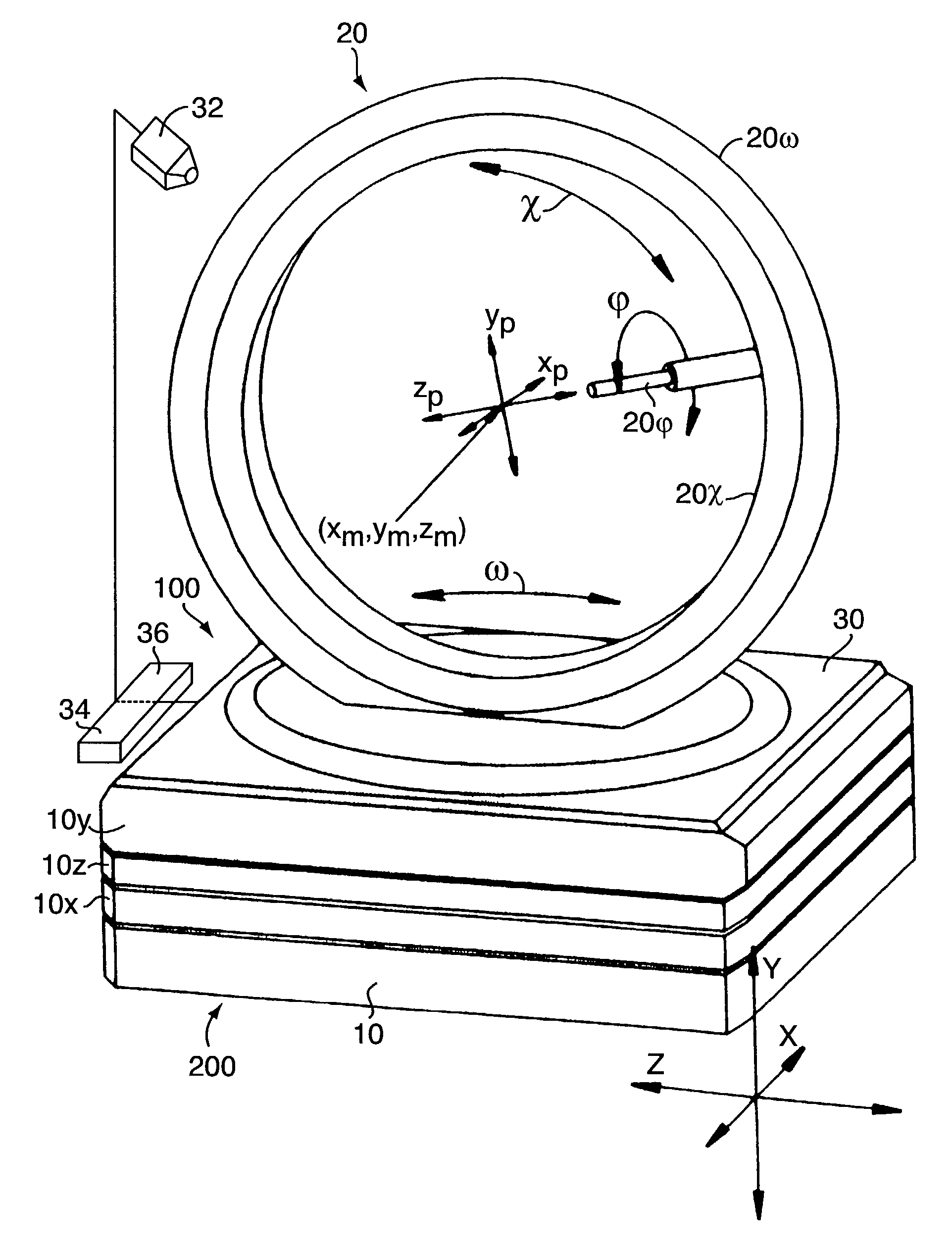
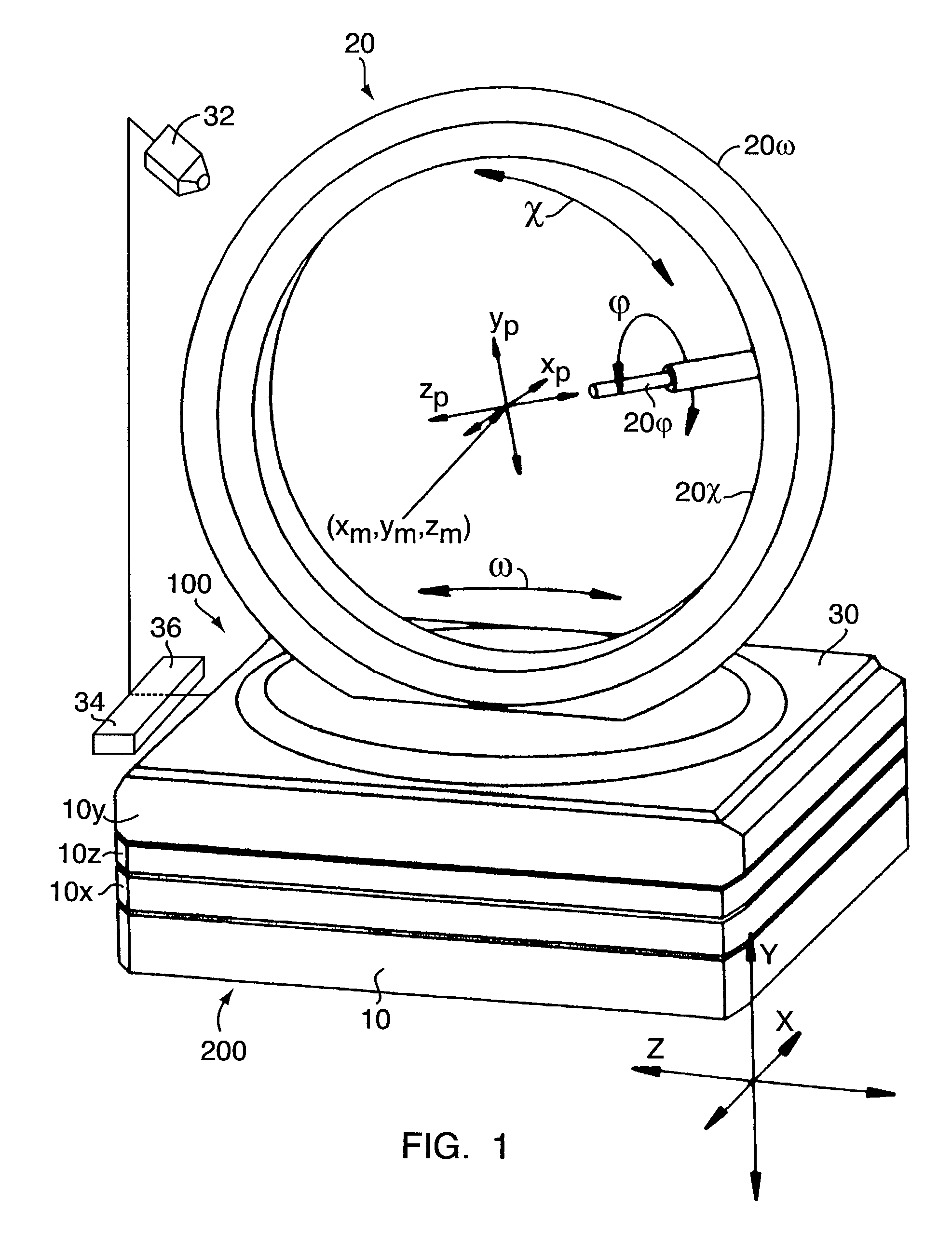
[0018] According to the instruction of this invention, therefore the centering is no longer executed statically but dynamically. While the above described techniques of conventional type always have the three essential components

[0019] translational adjusting of the center of the goniometer in the measuring point,

[0020] translational centering of the sample in the center of the goniometer and

[0021] rotational orientation or tilting of the sample during the measurement,

[0022] according to an inventive further development of the technique of ...


PUM


Abstract

In order to create a method for the automatic relative adjusting of the position coordinates (xp, yp, zp) of at least one sample with respect to the center coordinates (xm, ym, zm) of a goniometer (200) determined by the intersection point of the tilting axles (omega, chi, phi) as well as an associated device (100) through which the construction of goniometric systems is considerably simplified and moreover the costs for multiple circle systems are considerably reduced, it is proposed that, during a variation of the sample orientation or tilting, the trajectory of the sample which is taking place, in particular the precession trajectory of the sample, can be dynamically compensated about the center coordinates (xm, ym, zm) and the sample can be dynamically held at the measuring point, while [a] the trajectory of the sample about the center coordinates (xm, ym, zm) is recorded and exploited by digital image processing, [b] correction coordinates (xm-xp, ym-yp, zm-zp) are calculated from the exploited and recorded trajectory in order to dynamically compensate the trajectory and [c] the sample is moved according to the calculated correction coordinates (xm-xp, ym-yp, zm-zp) into at least one of the directions of translation (x, y, z) so that this translational shifting is dynamically coupled to the moving of the tilting axles (omega, chi, phi) of the goniometer (200) determined by the variation of the sample orientation or tilting.

Description

[0001] Applicant hereby claims foreign priority under 35 U.S.C. .sctn.119 from German Application No. 101 49 171.9 filed Oct. 4, 2001, the disclosure of which is herein incorporated by reference.[0002] This invention relates in general to the technical field of the centering of small samples by using standardized geometries; this invention relates in particular to a method for the automatic relative adjusting of the position coordinates of at least[0003] one sample which is on a sample holder or table of a goniometer,[0004] which is to be examined by means of the goniometer,[0005] which is movable in its position in at least one direction of translation and[0006] which is rotatable about at least one tilting axle in its orientation or tilting[0007] with respect to the center coordinates of the goniometer determined by the intersection point of the tilting axles.[0008] This invention furthermore relates to an associated device for the automatic relative adjusting of the position coor...

Claims


Application Information

Patent Timeline
IPC IPC(8): G01N23/20G01N23/207
CPCG01N23/20016
Inventor LENTFER, ARNO
Owner X RAY RES
Why Eureka
Try Eureka