
System and methods for controlling automatic scrolling of information on a display or screen

a technology of information display and screen, applied in the direction of mechanical pattern conversion, instrumentation, cathode-ray tube indicators, etc., can solve the problems of requiring the use of a hand in order to be controlled, and revealing disadvantages

Inactive Publication Date: 2003-01-30
LEMELSON JEROME H +1
View PDF0 Cites 109 Cited by
  • Summary
  • Abstract
  • Description
  • Claims
  • Application Information

AI Technical Summary

Benefits of technology

[0020] A further object of this invention is the gimbaled sensor system having a camera or photo sensor for providing images of the head and the eye of the user, a zoom lens coupled to the camera or photo sensor for focusing the camera or photo sensor at the user, and optics coupled to the camera or photo sensor for aiding the camera or photo sensor in detecting or providing images of the head and the eye of the user so that the images can be processed by the computer system.
[0031] A further of this invention is to provide a system for controlling the automatic scrolling of information on a display or a screen that allows the user to be able to freely use his or her hands to perform other tasks, procedures, work, etc.

Problems solved by technology

However, mouses require the use of hand or manual manipulation by the user and have the disadvantages in that they require the use of a hand in order to be controlled.
The disadvantages become evident when the user is in an environment which requires the simultaneous use of hands for other purposes (i.e typing on a keyboard) or requires a hands-free environment or the user is physically challenged or handicapped as to the use of his or her hands.
However, some of these devices still require manual or foot activation or selection to control the display of information, text, images, data, etc.
These type of devices still have the main disadvantage in that they require the use of a user's hand in order to be controlled.
Therefore, these devices are still not well suited for users that require a hands-free environment nor are they well suited to those users who are physically challenged.
The problem with this type of control of scrolling is that it is slow and requires the user to wait at least the pre-determined amount of time before scrolling is activated and implemented.
One of the problems with the eye tracking devices for eye controlled computer devices is that normally a mechanism is required to be attached to the user in order to track the movement of the user's eye(s).
Users, however, typically prefer not to have attachments on them in order to operate a computer peripheral since these attachments are usually uncomfortable to wear or they are not aesthetically pleasing, fashionable or ergonomic.
However, a problem with these non-attached eye tracking devices is that they only allow or restrict the movement of the user's head within a limited range since the hardware has to be directed or aimed within the range or vicinity of the user's eye.
However, these devices also do not in any way teach or suggest the control of automatic scrolling of a computer display or screen.

Method used


Image

  • System and methods for controlling automatic scrolling of information on a display or screen
  • System and methods for controlling automatic scrolling of information on a display or screen
  • System and methods for controlling automatic scrolling of information on a display or screen

Examples


Embodiment Construction

of a Specific Automatic Scrolling System

[0075] A. General Hardware for a Gimbaled Sensor System Screen Gaze Coordination for Automatic Scrolling System

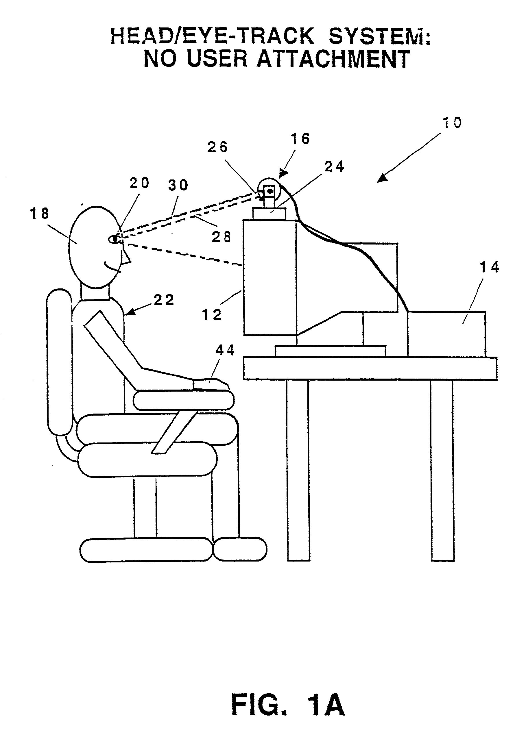
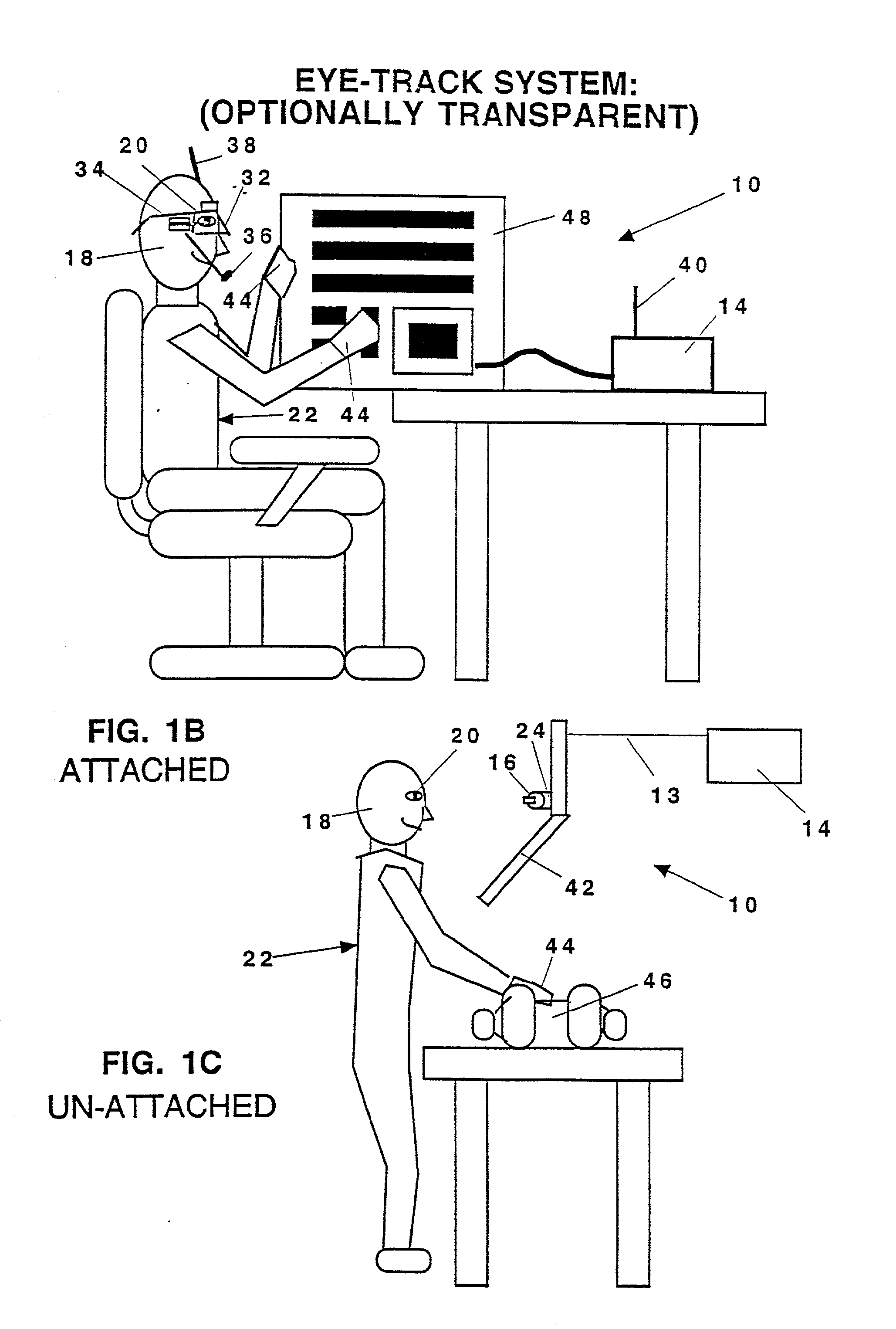
[0076] FIG. 3B shows a specific automatic scrolling system hardware 10 used for eye and head tracking that includes the use of a gimbaled sensor system 16 and pan / tilt servos represented at block 171 (i.e. pan and tilt servos 94 and 98 shown in FIG. 3C) that move the sensor(s) 15 that are components for the gimbaled sensor system 16. The computer system 14 is shown interfaced with the display system 52 (i.e. display system 12, 32, or 42), and the display system 52 is in front of the user(s) 22. A LAN or WAN 51 is also shown connected to computer system 14 for access to information on the internet. The gimbaled sensor system 16 tracks the head and eye movements of the user 22 and provides the advantage of the user 22 not having to wear or attach anything to him / herself. The overall human machine interface system 10 is able to track the...


PUM


Abstract

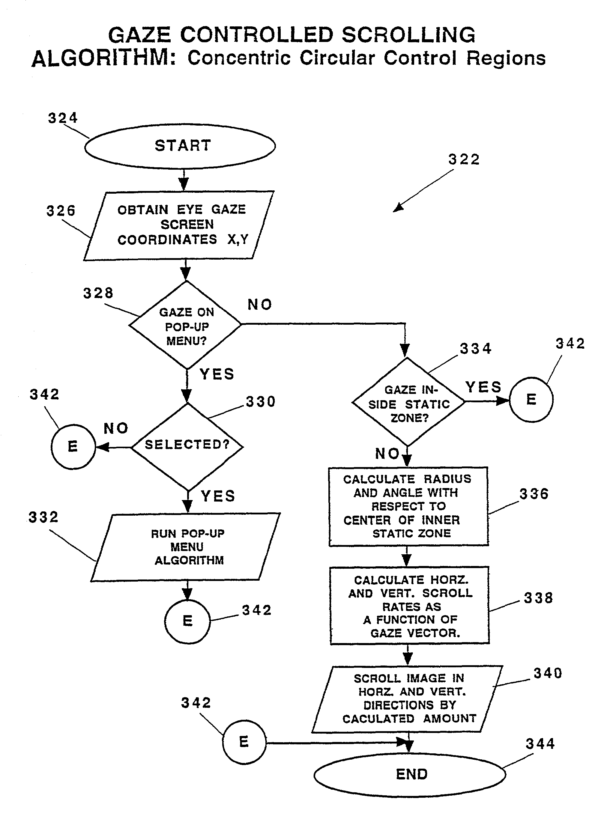
A system 10 for controlling the automatic scrolling of information on a computer display or screen 12 is disclosed. The system 10 generally includes a computer display or screen 12, a computer system 14, gimbaled sensor system 16 for following and tracking the position and movement of the user's head 18 and user's eye 20, and a scroll activating interface algorithm using a neural network to find screen gaze coordinates implemented by the computer system 14 so that corresponding scrolling function is performed based upon the screen gaze coordinates of the user's eye 20 relative to a certain activation area(s) on the display or screen 12. The gimbaled sensor system 16 contains a gimbaled platform 24 mounted at the top of the display or screen 12. The gimbaled sensor system 16 tracks the user's 22 head 18 and eye 20, allows the user to be free from any attachments while the gimbaled sensor system 16 is eye tracking, and still allows the user to freely move his or her head when the system 10 is in use. A method of controlling automatic scrolling of information on a display or screen 12 by a user 22 is also disclosed. The method generally includes the steps of finding a screen gaze coordinate 146 on the display or screen 12 of the user 22, determining whether the screen gaze coordinate 146 is within at least one activated control region, and activating scrolling to provide a desired display of information when the gaze direction is within at least one activated control region. In one embodiment, the control regions are defined as upper control region 208, lower region 210, right region 212, and left region 214 for controlling the scrolling respectively in the downward, upward, leftward, and rightward directions. In another embodiment, the control regions are defined by concentric rings 306, 308, and 310 for maintaining the stationary position of the information or controlling the scrolling of the information towards the center of the display or screen 12.

Description

[0001] This invention relates to a computer interface system and methods and their method of use, and, more particularly, to a computer interface system and methods for controlling automatic scrolling of information on a display or screen.[0002] Prior Conventional Computer Mouse Devices Computer interfaces such as mouses, track balls, light pens, etc. are devices that provide users with a way of controlling and manipulating the display of information, data, text, and images on a computer screen or monitor. Computer mouses have become a common and widely used device of present computer systems. It is well known that a mouse typically has a roller ball placed inside a hand-held housing wherein the ball rolls along a surface and the ball also rolls against directional control contacts to allow a user to move a cursor within a screen or monitor. The housing also usually has buttons on the top side for the user to activate user selection or to manipulate the display of information, data,...

Claims


Application Information

Patent Timeline
Patent Type & Authority Applications(United States)
IPC IPC(8): G06F3/00G06F3/01G06F3/033G06F3/048
CPCG02B27/0093G06F3/013G06F3/0485
Inventor LEMELSON, JEROME H.HIETT, JOHN H.
Owner LEMELSON JEROME H
Learn More