
Tool and method for straightening a door hinge

a door hinge and tool technology, applied in the field of tool and method for straightening a door hinge, can solve the problems of inaccurate adjustment, door will not close properly, and none of these disclosures address the problem of misalignmen

Inactive Publication Date: 2002-07-25
GOLDSTEIN STEVEN M
View PDF0 Cites 17 Cited by
  • Summary
  • Abstract
  • Description
  • Claims
  • Application Information

AI Technical Summary

Problems solved by technology

However, as the door ages, and even oftentimes with new doors, the door will not close properly.
The magnitude of force applied by the carpenter directly against the tool to bend the hinge is a matter of the carpenter's judgment so that the adjustment is not accurate.
None of these disclosures address the problem of misalignment of the door hinge that can occur after the dour is hung.

Method used


Image

  • Tool and method for straightening a door hinge
  • Tool and method for straightening a door hinge
  • Tool and method for straightening a door hinge

Examples


Embodiment Construction

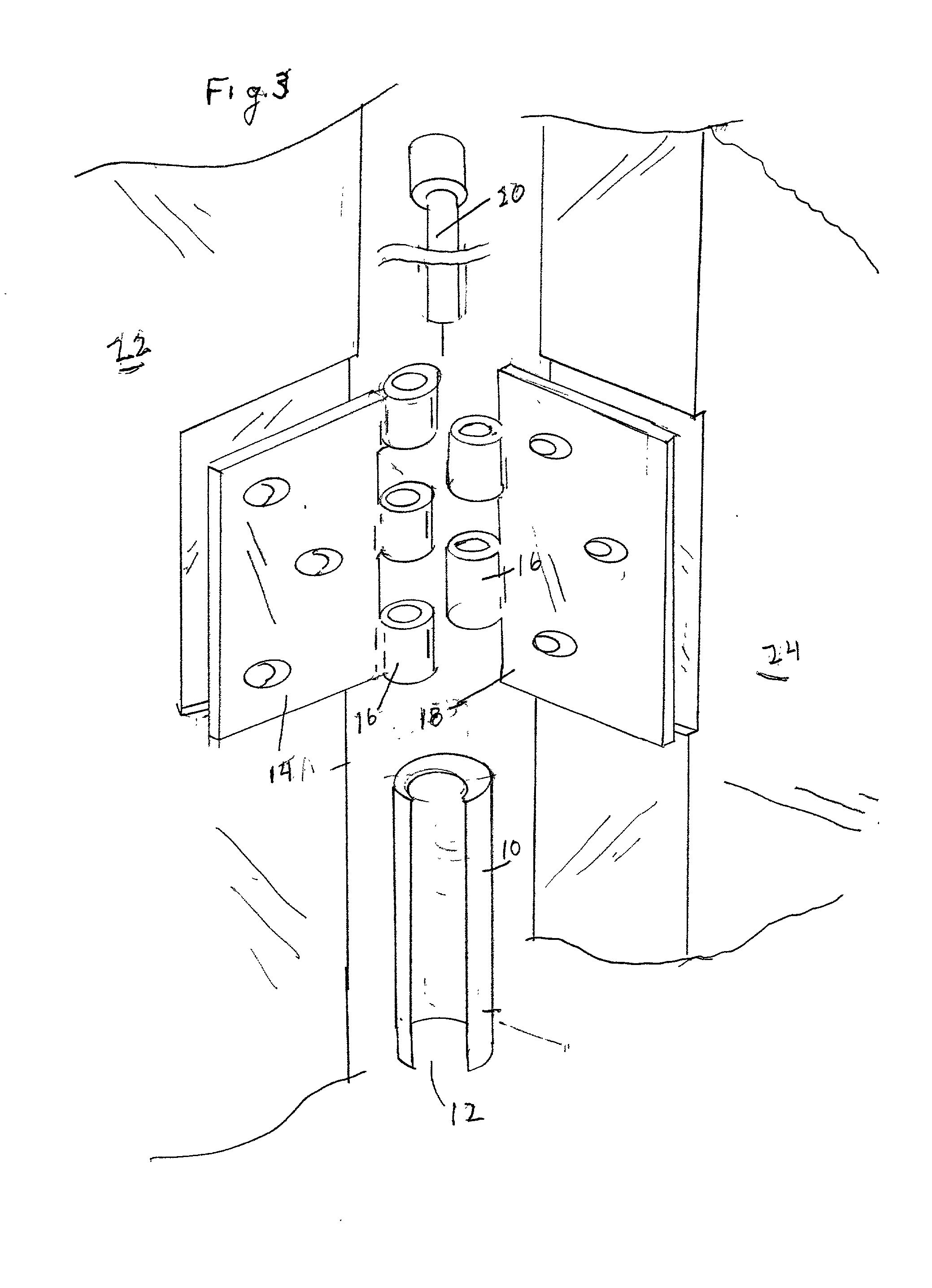
[0018] Turning now to a discussion of the drawings, FIG. 3 is a perspective exploded view illustrating the invention. The tool is a tube 10 having an offset center with a slot 12 extending from one end to the other end of the tube 10. The door 24 and door frame 22 (cutaway) are shown. The parts of the hinge are also shown including a first hinge plate 14 with knuckles 16 and a second hinge plate 18 with knuckles 16. Hinge pin 20 slides through the knuckles 16 when the hinge is assembled. First hinge plate 14 is attached to the door frame 22 and the second hinge plate 18 is attached to the door 24.

[0019] FIG. 4 is a plan view showing the tube 10 slid over the assembled hinge. The pin 20, (in phantom), extends through the knuckles 16 (shown in phantom) so that the edge of door 24 abuts door frame 22.

[0020] FIG. 5 is a flow chart listing the steps in the method of this invention for aligning the door hinge.

[0021] In step 1, the tool of FIG. 3 is provided being a tube with a slot extend...


PUM


Abstract

A tool for adjusting a door hinge so that the door hangs properly. The tool is a tube with a slot extending from one end of the tube to the other end of the tube and having a bore to permit sliding the tube over the knuckles of the door hinge. In use, the tube is slid over the knuckles of the hinge with the plates of the hinge extending through the slot. The door is opened sufficiently so that the swage and / or mounting plate are adjusted to where the door swings and closes properly.

Description

[0001] This invention relates to adjusting door hinges and particularly to a tool that slides onto an installed door hinge and straightens the door hinge.BACKGROUND AND INFORMATION DISCLOSURE[0002] The typial door hinge 11, shown in FIG. 1, includes two hinge plates 14, 18, and a hinge pin 20. Each hinge plate 14, 18 has one or more knuckles 16 that are aligned with the one or more knuckles 16 of the other hinge plate. The hinge pin through the knuckes secures the hinge plates 11 together,[0003] Most metal doors and door frames have hinges attached to a mounting plate which is secured to the door frame.[0004] A crossection of the assembled hinge 11 is shown in FIG. 2. A bend 21 in each hinge plate (called a "swage") is formed in order that, when the door is closed, the door will close properly.[0005] However, as the door ages, and even oftentimes with new doors, the door will not close properly.[0006] A number of devices have been disclosed related to the mounting of doors on door f...

Claims


Application Information

Patent Timeline
IPC IPC(8): E05D7/00E05D11/00
CPCE05D7/04E05Y2800/692E05Y2900/132Y10T29/24
Inventor PAWSON, ERIC C.
Owner GOLDSTEIN STEVEN M
Learn More