
Automatically adjustable landing lights for aircraft

a technology of automatic adjustment and landing lights, which is applied in the direction of aircraft landing aids, transportation and packaging, aircraft components, etc., can solve the problems of misalignment between the aircraft nose and the runway heading, adversely affecting the operation and performance of the aircraft at the aerodrome, and limited landing light systems

Active Publication Date: 2022-07-05
HONEYWELL INT INC
View PDF68 Cites 0 Cited by
  • Summary
  • Abstract
  • Description
  • Claims
  • Application Information

AI Technical Summary

Problems solved by technology

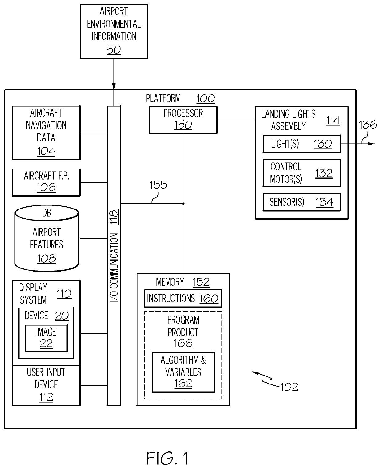
First, landing light systems generally activate, or illuminate terrain, only in response to manual interaction (e.g., manipulation of an on / off switch) by the crew.
In addition, landing light systems are often limited to a static location of illumination and a static area of illumination on an aerodrome.
As a result, in practice, the airport environmental conditions can adversely affect the operation and performance of the aircraft at the aerodrome.
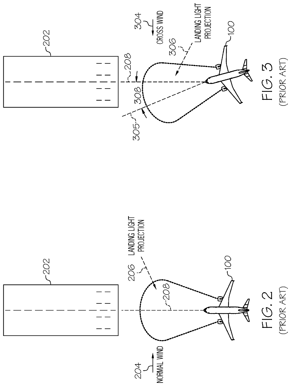
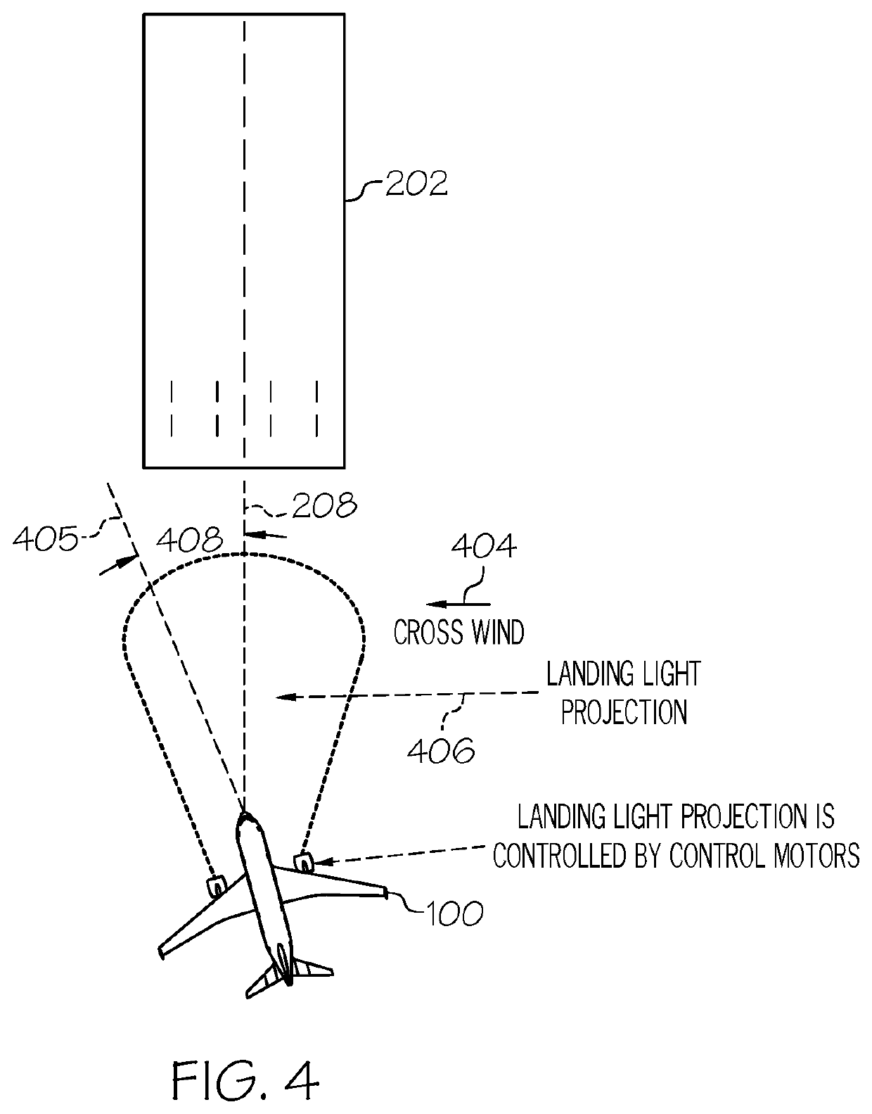
For example, during the final approach phase, ground wind and temperature can affect aircraft flight plan data, such as the aircraft orientation / heading, causing a misalignment between the aircraft nose and the runway heading.
These and other problems illustrate technological limitations associated with available landing light systems.
These technological limitations often require the crew to make frequent visual checks of the actual ground track of the aircraft, and to make manual wind corrections as necessary.

Method used


Image

  • Automatically adjustable landing lights for aircraft
  • Automatically adjustable landing lights for aircraft
  • Automatically adjustable landing lights for aircraft

Examples


Embodiment Construction

[0016]The following detailed description is merely illustrative in nature and is not intended to limit the embodiments of the subject matter or the application and uses of such embodiments. As used herein, the word “exemplary” means “serving as an example, instance, or illustration.” Thus, any embodiment described herein as “exemplary” is not necessarily to be construed as preferred or advantageous over other embodiments. The embodiments described herein are exemplary embodiments provided to enable persons skilled in the art to make or use the invention and not to limit the scope of the invention that is defined by the claims. Furthermore, there is no intention to be bound by any expressed or implied theory presented in the preceding technical field, background, summary, or the following detailed description.

[0017]As mentioned, dynamic airport environmental conditions can evince the technological limitations of available landing light systems. Multiple variations of crosswind and te...


PUM


Abstract

An automatically adjustable landing light circuit and method for an aircraft approaching a target are provided. The circuit includes a memory having therein an auto adjustable landing light program, and a processor operationally coupled to a source of real-time navigation data, a source of intended approach information, a source of target geometry, and a source of environmental information including cross-wind data. The processor executes the auto adjustable landing light program, to: determine a course correction, as a function of the cross-wind data, upon determining each occurrence of deviations exceeding respective thresholds for the current heading and an intended heading, the current pitch and an intended pitch, and the current yaw and an intended yaw. The processor generates control motor commands for a landing lights assembly that generates a landing light projection. The control motor commands adjust the landing light projection in accordance with each determined course correction.

Description

TECHNICAL FIELD[0001]The technical field generally relates to landing light systems for aircraft, and more particularly relates to landing light circuits and methods for aircraft that automatically adjust (auto adjustable) as a function of environmental factors and aircraft navigational data.BACKGROUND[0002]Landing light systems, having therein at least one landing light, are mounted on aircraft and are primarily activated to illuminate the terrain and runway ahead during takeoff and landing. As may be appreciated, landing lights are primarily useful during the night, to enhance the crew visibility on the forward view. The crew relies on appropriate functionality of the landing light system to make time critical decisions during normal or low visibility conditions.[0003]Available landing light systems generally provide the following functionality for an aircraft. First, landing light systems generally activate, or illuminate terrain, only in response to manual interaction (e.g., man...

Claims


Application Information

Patent Timeline
Patent Type & Authority Patents(United States)
IPC IPC(8): B64D47/04B64D43/00B64D45/08
CPCB64D47/04B64D43/00B64D45/08
Inventor SHAMASUNDAR, RAGHU
Owner HONEYWELL INT INC
Learn More