
Magnetic resonance imaging method with hybrid filling of k-space

a magnetic resonance imaging and hybrid filling technology, applied in the field of magnetic resonance imaging, can solve the problem of rapid decrease in scan efficiency, and achieve the effect of improving scan efficiency, minimizing image quality loss, and optimizing image fidelity and scan duration

Active Publication Date: 2022-01-04
ETH ZZURICH +1
View PDF6 Cites 0 Cited by
  • Summary
  • Abstract
  • Description
  • Claims
  • Application Information

AI Technical Summary

Benefits of technology

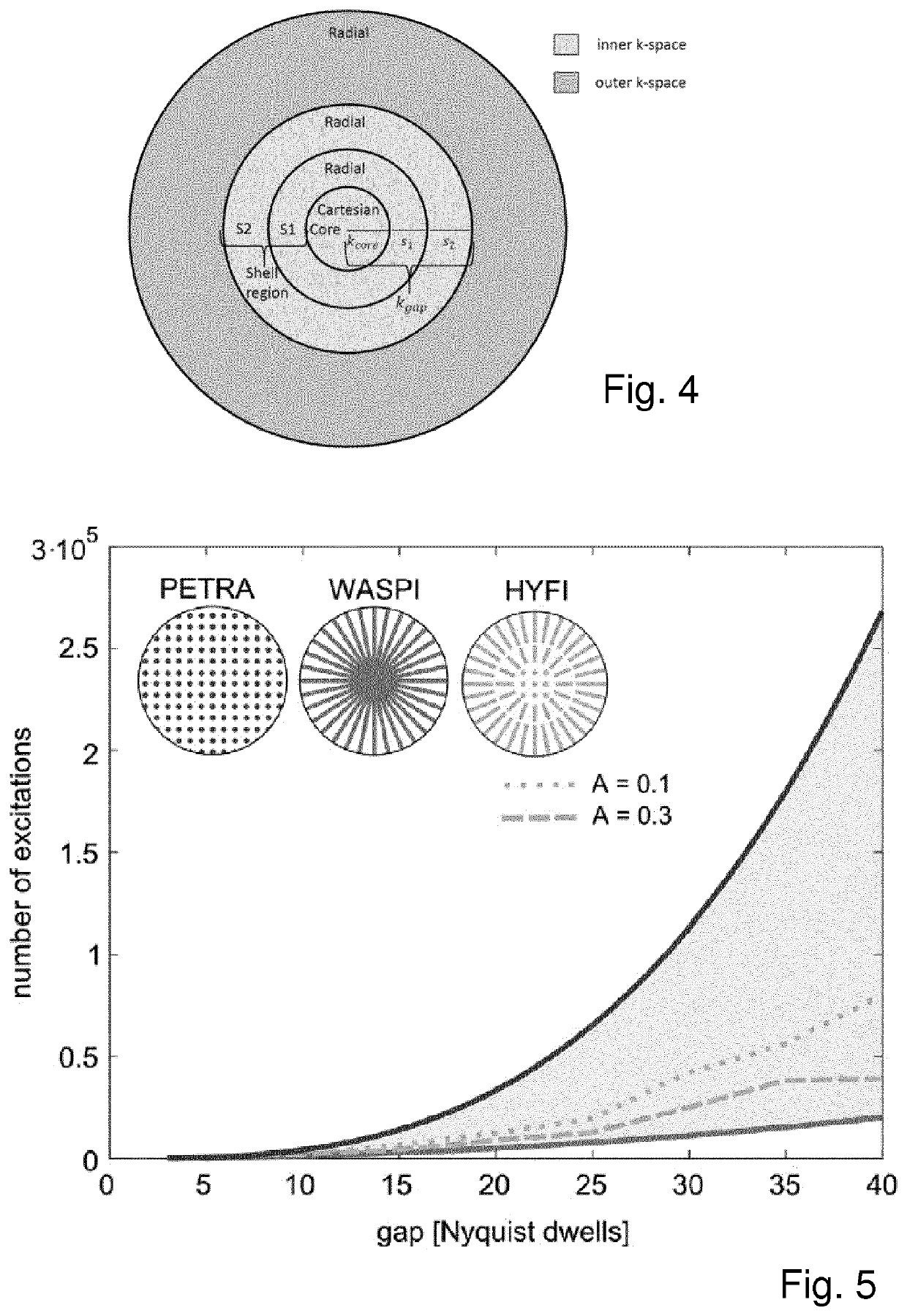
[0025]By virtue of the fact that the inner k-space region is subdivided into a core region and at least one radially adjacent shell region, with raw data points in the core region being acquired as Cartesian raw data, and raw data points in the shell region being acquired along radial k-space trajectories using a gradient strength G that is smaller than the gradient strength G0, it is possible to optimize image fidelity and scan duration under given circumstances.
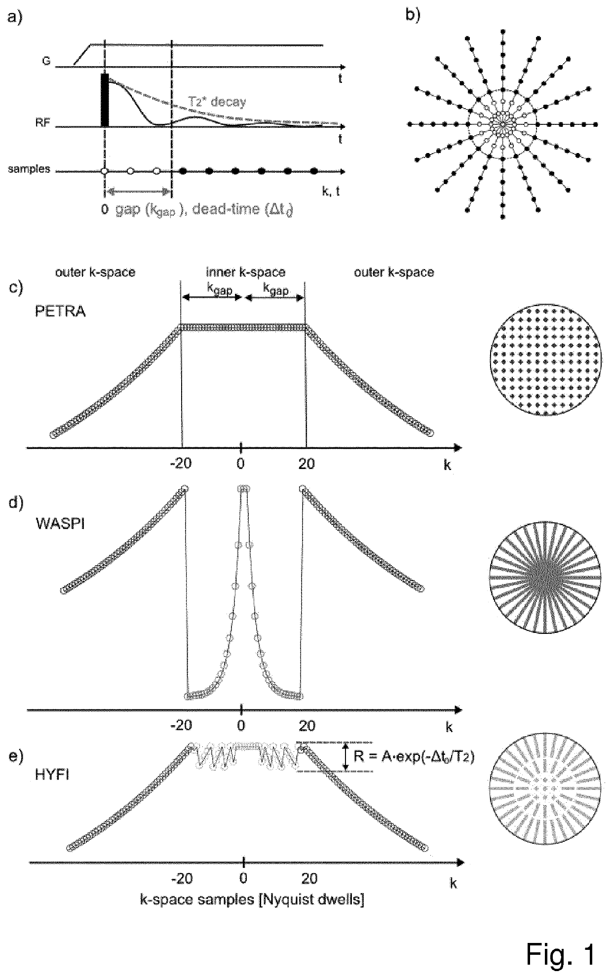
[0026]The method of the present invention will henceforth be addressed as hybrid filling and abbreviated as “HYFI”. The HYFI approach improves scan efficiency at large gaps with minimum loss of image quality.
[0037]With the above definition, one can limit Cartesian acquisition to a small core region and thus allow using the more efficient radial acquisition wherever possible.

Problems solved by technology

However, its scan efficiency decreases quickly with gap size.

Method used


Image

  • Magnetic resonance imaging method with hybrid filling of k-space
  • Magnetic resonance imaging method with hybrid filling of k-space
  • Magnetic resonance imaging method with hybrid filling of k-space

Examples


example

[0105]A comparison of magnetic resonance imaging acquired with PETRA (state of the art), WASPI (state of the art) and HYFI (present invention) is shown in FIG. 7. Magnetic resonance imaging was performed with PETRA (equivalent to HYFI with A=0), WASPI (equivalent to HYFI with A=1) and HYFI (A=0.2).

[0106]First Row: 1D representations of the signal T2-weighting in k-space. The signal amplitude in the outer k-space region is exponentially decaying and equivalent in all techniques. However, the acquisition of the inner k-space region is specific to each technique. In PETRA, the signal is acquired point by point at a constant time following the spin excitation leading to a constant T2-weighting in the inner k-space region. In WASPI, the inner k-space region is read out radially with a reduced gradient strength causing stronger signal decay and amplitude jumps at the border separating inner and outer k-space regions. In HYFI, the inner k-space region is split into several sub-regions: a c...


PUM


Abstract

A method for generating an image data set of an image area located in a measurement volume of a magnetic resonance system comprising a gradient system and an RF transmission / reception system, comprises the following method steps: —reading out k-space corresponding to the imaging area, by: (a) activating a frequency encoding gradient in a predetermined spatial direction and with a predetermined strength G0 by means of said gradient system, (b) after the activated frequency encoding gradient achieves its strength G0, radiating a non-slice-selective RF excitation pulse by means of said RF transmission / reception system, (c) after a transmit-receive switch time ΔtTR following the radiated excitation pulse, acquiring FID signals with said RF transmission / reception system and storing said FID signals as raw data points in k-space along a radial k-space trajectory that is predetermined by the direction and strength G0 of the frequency encoding gradient, (d) repeating (a) through (c) with respectively different frequency encoding gradient directions in each repetition until k-space corresponding to the image area is read out in an outer region of k-space along radial k-space trajectories, said radial k-space trajectories each having a radially innermost limit kgap which depends on said switch time ΔtTR, (e) reading out a remainder of k-space that corresponds to the imaging area, said remainder being an inner region of k-space not being filled by said first region and including at least a center of k-space, in a read out procedure that is different from (a) through (d), and storing all data points read out in (d) and (e); and —reconstructing image data from the read out data points in k-space by implementing a reconstruction algorithm; In order to constrain image fidelity and optimize scan duration under given circumstances, the inner k-space region is subdivided into a core region and at least one radially adjacent shell region.

Description

CROSS-REFERENCE TO RELATED APPLICATIONS[0001]This is the U.S. national stage of International application PCT / EP2018 / 077361, filed Oct. 8, 2018 designating the United States and claiming priority to European application EP 17195568.5, filed Oct. 9, 2017, both of which are incorporated herein by reference in their entireties.FIELD OF THE INVENTION[0002]The present invention generally relates to a method of magnetic resonance (MR) imaging. More specifically, it relates to a zero echo time imaging method useful for MRI of tissues with short coherence lifetimes.BACKGROUND OF THE INVENTION[0003]Direct imaging of tissues with short transverse relaxation times (T2 or T2*) is interesting both from a scientific and also from a clinical point of view (see [1] and references cited therein). It is known that imaging of samples with relaxation times shorter than a few milliseconds requires specialized imaging methods, which most notably include zero echo time (ZTE) based techniques such as algeb...

Claims


Application Information

Patent Timeline
Patent Type & Authority Patents(United States)
IPC IPC(8): G01R33/48A61B5/055G01R33/561
CPCG01R33/4822A61B5/055G01R33/4816G01R33/5618G01R33/4824G01R33/54
Inventor FROIDEVAUX, ROMAINWEIGER, MARKUS
Owner ETH ZZURICH
Learn More