Device for transporting items

a technology for items and carts, applied in the direction of hand cart accessories, hand carts with multiple axes, clothing, etc., can solve the problems of difficulty in carrying by shoppers, and achieve the effect of better handling, easy steering and more controllable control

Active Publication Date: 2021-06-29
TRASGATE LTD
View PDF74 Cites 2 Cited by
  • Summary
  • Abstract
  • Description
  • Claims
  • Application Information

AI Technical Summary

Benefits of technology

[0014]This arrangement allows a user to use the device as a basket in the basket configuration and as a trolley in the trolley configuration. In the basket configuration, the handle is positioned above a central portion of the open top of the basket, meaning that when held off the ground by the handle, the centre of gravity aligns itself beneath the horizontal part of the handle. Thus, placing the handle over a central portion of the basket portion allows a user to conveniently pick up and carry the device, because it can help to keep the basket portion flat while it is being lifted, so a user does not need to strain to keep items inside the basket, or indeed to retain the ordering inside the cavity against a tilting as the basket is lifted (as would be the case, for example when the centre of gravity is not broadly below the handle). In this context, a central portion is located between the front and the rear of the basket portion. The positioning may be chosen to ensure that, when lifted by the handle (such that the centre of mass hangs below the horizontal part of the handle), the rim at the edge of the open top of the basket portion makes an angle of no more than about 25° to 30° with the horizontal (in this case, “the horizontal” is defined as being perpendicular to the direction of the local gravitational field). In other cases, the central portion may be defined as being in the middle third of the basket portion as measured from front to back. The horizontal portion of the handle needn't extend perpendicularly across the width of the basket portion, but can extend across the width of the basket portion such that the whole horizontal portion of the handle lies over the middle third of the basket portion. For example, the horizontal portion may extend across the basket in such a way that it runs in a direction which has a component along the length of the basket portion, in addition to extending across the width of the basket portion. Such a device may also provide the benefit that it can be easily loaded into a car as it is folded, as set out in more detail below. Generally cuboidal in this context means having a well-defined, broadly planar opposing sides, a front, a rear opposite the front, and at least a base (optionally a lid too). The sides are approximately orthogonal to the opposing front and rear and also to the base, and the front and rear are approximately orthogonal to the base. Small deviations from the sides, front, rear, and base being exactly planar or meeting one another at slightly rounded corners, or at an angle differing from 90° by a small amount are all examples of shapes encapsulated by the phrase “generally cuboidal”.
[0042]The device may further comprise one or more hooks on the exterior of the basket portion, for example to allow additional bags, a user's coat, etc. to hang from during use. Additionally or alternatively, the device may be provided with a pocket or pouch on the exterior of the basket, for example for storing keys, coins, etc. while shopping. In some cases, a roll up plastic hood may be provided in a storage pouch or other suitable storage means, the plastic hood being sized for covering the open top, e.g. to protect the cavity from getting wet when it is raining.

Problems solved by technology

However, a shopper often finds themselves taking more items than they had anticipated which can overload the basket and make it difficult for the shopper to carry.

Method used


Image

  • Device for transporting items
  • Device for transporting items
  • Device for transporting items

Examples


Embodiment Construction

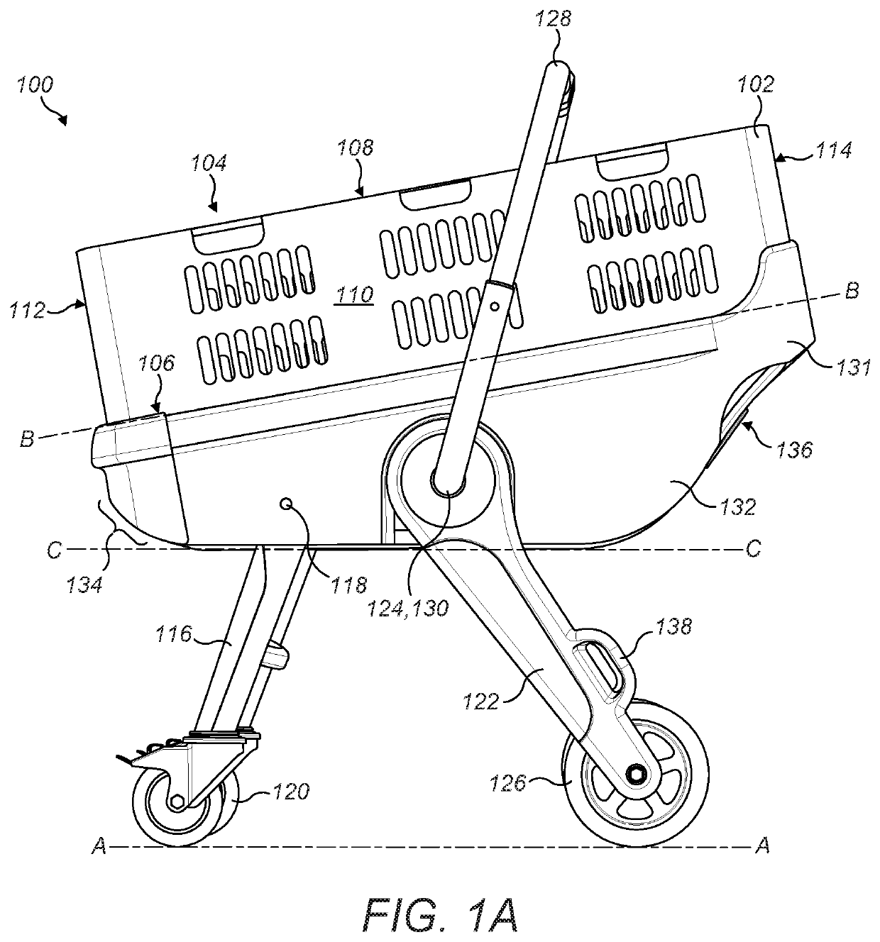
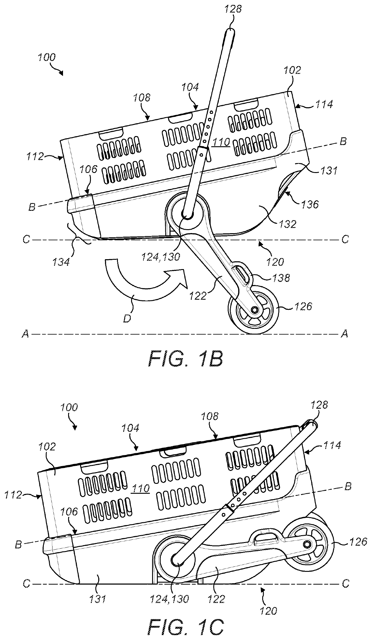
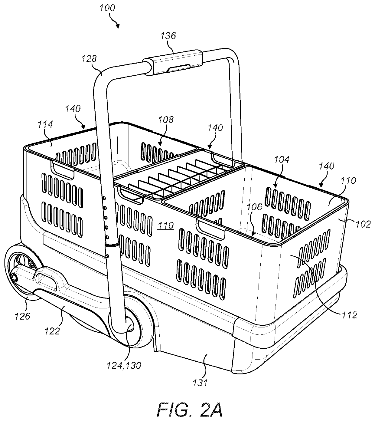
[0050]Consider FIGS. 1A to 1C, which shows a device 100 according to the present disclosure as it transitions from the trolley configuration in FIG. 1A to the basket configuration in FIG. 1C. Starting with FIG. 1A, it can be seen that the device 100 has a basket portion 102 at its top, that is to say the basket portion 102 is spaced apart from the ground (which is denoted by dashed line (A), representing, for example, the plane of the ground). The basket portion 102 has a generally cuboidal shape, having a front wall 112, rear wall 114, side walls 110 and an open top 108. A base 106 provides closure to the lowermost part of the basket portion 102. The entire basket portion 102 is tilted with respect to the ground, as is shown by dashed line (B), representing the location of the plane of the base 106 of the basket portion 102, which clearly slopes with respect to the plane of the ground (A). The base 106, side walls 110, front wall 112 and rear wall 114 define a cavity 104 which is a...


PUM


Abstract

A device has a cuboidal basket portion defining a cavity. A front pair of legs is attached to the basket portion such that the front legs are pivotable about a first axis, and each front leg has a wheel. A rear pair of legs is attached to the basket portion such that the rear legs are pivotable about a second axis, and each rear leg has a wheel. A handle is attached to the basket portion and is pivotable around a third axis. The device has a basket configuration in which the handle is located across and above the basket portion and the legs are collapsed with the wheels located adjacent to a base of the basket portion. The device has a trolley configuration in which the handle is located rearward of the basket portion and the legs are extended for supporting the basket portion.

Description

[0001]The present disclosure relates to devices for transporting items, and particularly to devices for transporting shopping, groceries and the like. In particular, the disclosure describes devices having a trolley configuration and a basket configuration.BACKGROUND TO THE INVENTION[0002]Commonly, shoppers navigate supermarkets and shops to retrieve items such as groceries, hardware, etc. from shelves to take those items to a cashier. In order to transport these to the cashier, shoppers often find it convenient to use a basket or trolley (a “shopping cart” in American English). Often these are provided by the shop, but a shopper must decide at the entrance to the shop whether to take a basket or a trolley around the shop with them. A basket may be preferred when relatively few items are desired, as the basket may be less cumbersome to manoeuvre around the shop than a trolley is. However, a shopper often finds themselves taking more items than they had anticipated which can overload...

Claims


Application Information

Patent Timeline
Patent Type & Authority Patents(United States)
IPC IPC(8): B62B3/02B62B3/00B62B5/00B62B5/06
CPCB62B3/027B62B3/005B62B5/0003B62B5/0013B62B5/067B62B3/1464B62B2205/12A45C3/04B62B3/02B62B3/18B62B2205/30
Inventor STROH, ISAAC
Owner TRASGATE LTD
Why Eureka
Try Eureka